Rick Mur

Limitless Networking

Page 2 of 10

JNCIE-DC lab in EVE-NG

As explained in my previous post on my home servers, I have a bare metal system deployed with EVE-NG Pro installed. As I’m (slowly) preparing for the JNCIE-DC certification I wanted to share the topology that I’m using.

As the hardware required to study for the JNCIE-DC is quite significant, it makes a lot of sense to try and virtualise most of these resources. Unfortunately not the entire blueprint can be tested with virtual appliances, but we can get a very long way. Some (or a lot of) experience with actual Juniper QFX and MX products is very useful in your preparation for the JNCIE-DC.

Juniper offers a very good self-study product for the JNCIE-DC. This self study workbook contains a number of chapters with in-depth tasks on a certain topic of the lab blueprint and also contains 2 full labs that are very similar in complexity to the real JNCIE-DC lab test.

At the time I’m writing this, there are (as far as I know) no options to rent a rack of physical hardware to prepare for the exam, because the self-study workbook offered by Juniper Education Services also uses a virtual lab topology based on the vMX and vQFX products.

The lab topology used in that self-study workbook is used in my topology as well, so you are able to do all labs in that workbook on this topology as the same virtual appliances are used.

JNCIE-DC Lab Device Blueprint

Let’s first take a look at the blueprint of the JNCIE-DC lab exam to know what topics are covered and what type of devices are used when you take the exam.

An important prerequisite is that you need a valid JNCIP-DC certificate to be able to schedule a lab date with Juniper.

The lab exam consists of a number of the following devices:

  • QFX5100 running Junos 14.1
  • MX80 running Junos 17.1
  • vMX running Junos 15.1
  • vSRX running Junos 12.1

Feature wise there should not be much difference between the MX80 and vMX devices as the Packet Forwarding Engine (PFE) is also virtualized in the vMX. They do run a different version of Junos, so that could be a thing to be aware of. Regarding features or maybe configuration that may have changed between these versions.

At time of this writing in 2020, the Junos versions running in the lab are quite old. They are still up to date as I’m not aware of any annoucement of an update to the blueprint or the versions in the lab. The versions are even that old that most of them are not available anymore to download from the Juniper website.

You can also clearly see that the lab consists of a combination of physical devices and virtual devices. Again, when configuring the tasks you will not (or should not) feel any difference in the handling and operation of the devices.

Juniper lab exams are also known to have extra devices in the topology that you will not have access to and do not have to configure, but where you will need to interface with and setup some form of connectivity with. They will act as external routers (like an Internet connection) or a remote site to interconnect with. So be prepared to know how to check connectivity issues from one side (like how to troubleshoot BGP adjacency issues for example from the local router, without knowing the configuration of the other side).

I would expect the devices in the lab to also have an initial configuration already present. You may even have to troubleshoot this as there could be a mistake in there on purpose.

In this post I will not cover the task blueprint as the Juniper website has a very detailed overview of the possible tasks and topics that are covered in the test.

JNCIE-DC lab in EVE-NG

The tasks of the self-study workbook are all based on virtual appliances, as mentioned before. We will use a multiple of vMX and full vQFX devices. The vQFX comes in 2 flavours: Lite and Full. The lite version only contains a routing-engine, which enables you to test routing features. For anything else than layer 3 routing (to test IP fabrics for example), you will need the full version which adds a second VM that runs a virtualised version of the Q5 chipset. These 2 VMs combined (just like with the vMX), run a full version of a QFX10000 type switch. Unfortunately this is not a QFX5100 based switch (which is based on Broadcom Trident 2 silicon). The main difference in configuration between the QFX10k (with Juniper silicon) and the QFX5100 is how layer 2 bridge domains and therefore EVPN configuration is handled, so before taking the test be aware of the limitations the QFX5100 has (hint: one ‘virtual’ switch vs multiple).

To be able to run the full topology that the workbook uses you will need:

  • 6 vMX routers
  • 6 vQFX switches
  • 1 vSRX firewall
  • 1 Junos Space VM
  • 1 Linux VM

As both the vMX and vQFX require 2 VMs per device, it means we will need a total of 27 virtual machines to run the full topology. As you can imagine, this will consume quite a lot of resources on your system. I would recommend getting at least an 8 core CPU and 64GB RAM. The RAM requirement can be a bit lower as EVE-NG has excellent memory dedub features. The CPU core count is really the more the better. If you are able to run this lab running for a long time it’s not that big of a deal. Especially when booting everything up, a higher CPU core count is very welcome.

There is one important item that cannot be tested on the virtual appliances and that is Virtual Chassis Fabric, which is not supported on the QFX10000. The commands involved to get this up and running are not that much and the workbook offers a good explanation of it that should be enough for the lab exam.

JNCIE-DC Lab Topology

There are quite a number of connections to take care of. My good friend Valentijn Flik made a diagram of the topology as my versions turned out more like spider webs.

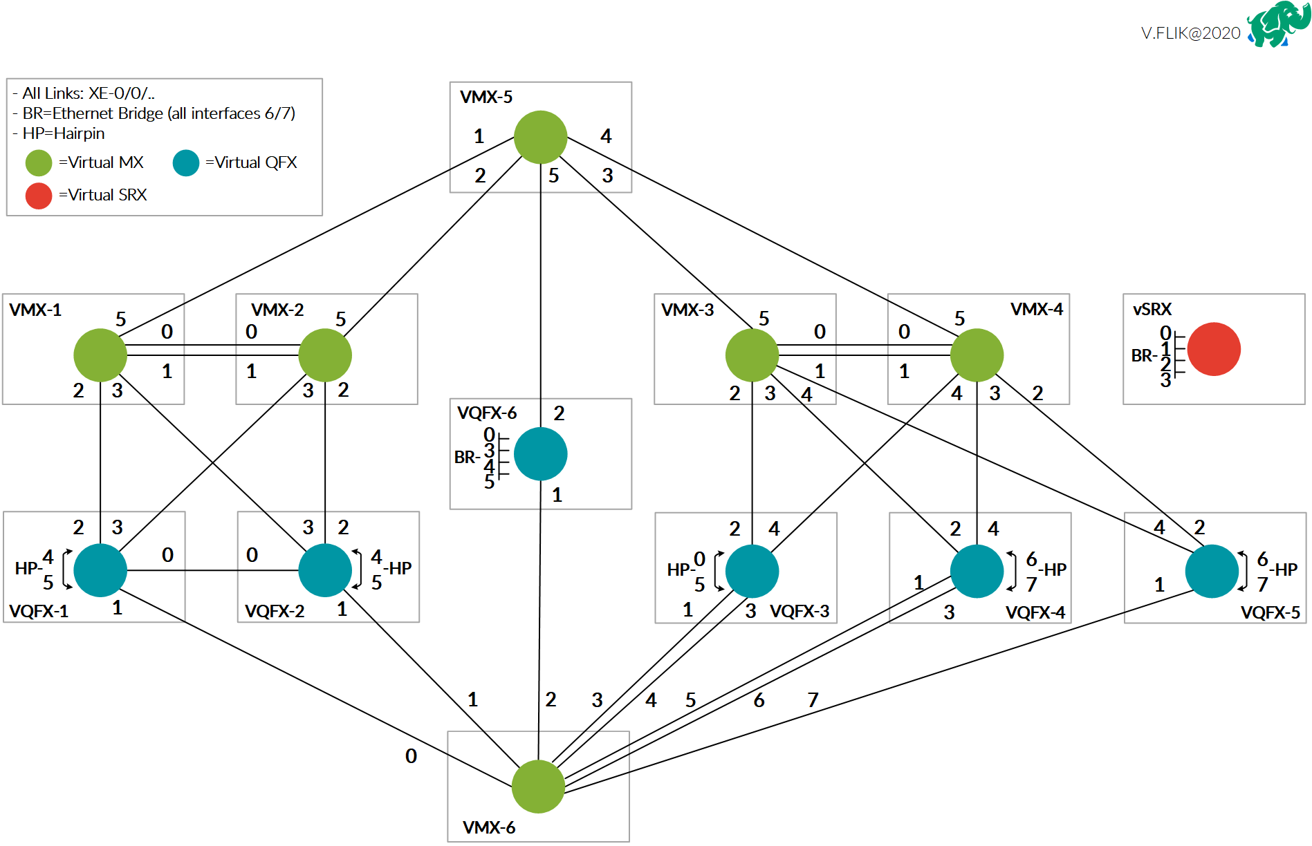
The main topology is seen as being 2 datacenter sites. One contains 2 vMX routers as spines and 2 vQFX switches as leafs. The second contains 2 vMX routers and 3 vQFX switches in a more typical CLOS fabric wiring. All devices have connections to either vMX5 or vMX6 for ‘backbone’ or external connectivity testing. The top vMX5 will be used more as peering or external connection router and the bottom vMX6 is more used as a simulation of network hosts in the setup.

Some devices have connections that loop back into the same device. These are called hairpin connections.

All devices have ports 6 and 7 also connected to an Ethernet Bridge. Using this bridge segment the lab tasks make use of 802.1Q or VLAN tags to simulate connections between devices that are not actually there. You do not need to make this on your own, as the initial configuration provided by the workbook will take care of this when you load up the configs for a certain task. The bridge in EVE-NG that I used is just a standard bridge network, which should be sufficient for all tasks.

I have also connected all devices out of band management interface to a virtual bridge that connects to my home LAN network so I can reach all devices over their OOB IP address.

Software

There are a number of software images involved with this set-up. The virtual appliances are available for download on the Juniper website. The best way to find them is via the trial options that are available:

As far as Junos versions are considered, I use very recent versions of the appliances, actually the newest at time of this writing. I do not expect behavior to be very different between the releases running in our lab versus the actual lab exam.

You will also want a Junos Space VM if you really want to test the entire blueprint, but you will need a Juniper account with software download access to get access to that. Fortunately the self-study workbook also comes with a number of vouchers to use the Juniper provided virtual environment, which should be more than enough exposure to Junos Space to be able to understand it fully.

As for licensing, the vMX has a default bandwidth limit of 1Mbps, which is more than enough for the lab testing. On the vQFX I’m not aware of any licensing limitations, only that the platform is only capable of a very low packets per second performance, so again perfect for testing! Finally the vSRX does have a time constraint without having a license installed. The system will not work anymore after 60 days, but this is easily reset by deleting and re-adding the device to your topology and as all tasks start with a fresh or initial setup, there is no problem in deleting and adding the device again. You will not lose work as I would recommend saving your lab configs after you finished the task, as it’s a great resource to check back on during your studies.

Using the lab

You can download my EVE-NG lab here, be aware that you will need to make your own device definitions first based on software images downloaded earlier.

I would suggest following the documentation on the EVE-NG website to setup the appliances:

After creating the Juniper virtual appliance templates in EVE-NG, it’s time to import or create the JNCIE-DC lap topology. I would recommend creating it yourself as you immediately learn a lot about which connections run where and it sets you up learinng the topology quicker.

Then the last part that’s required are the JNCIE-DC self-study workbook initial configurations. As the book and it’s resources are copyrighted I cannot share them here, but I downloaded them from the Juniper virtual environment. After purchasing the workbook you get a number of vouchers that allow you to schedule for a full day of lab access. If you log on to the Linux virtual machine, there is a folder with all workbook configurations on the drive. That VM should have access to the Internet, so you can store a zip file of that folder it on any file sharing website for use within your lab setup.

Happy Labbing

Now when all VMs are booted, you can dig into the workbook and load initial configurations of each chapter and start labbing! Feel free to use the lab topology diagram and/or the EVE-NG lab template for your own use and adjust for your own preferences when desired!

If you have any questions regarding the JNCIE-DC lab, running it on EVE-NG or have any JNCIE-DC study questions in general. Feel free to reach out below in the comments or via Twitter!

Home Network 2020

Recently I moved to a new house and as a lot of reconstruction was done to bring the house up to date. I took the opportunity to have something I’ve always wanted in my home: a server rack! In my previous lab set-ups they were either located in my employers lab location or placed in a storage space. Now I had the opportunity to really make something nice for myself.

The rack contains both the equipment for running the automation and infrastructure in the house and my home lab. In this post I’d like to show some details of the equipment in it and the basic infrastructure that is running on it.

Location

On top of my garage is an attic that exactly fits a 15RU rack. As my home office is built right below it I had to take care of sound levels, so no high-rpm 40mm fans.

After taking away the top and bottom of the rack it could fit exactly! All Cat.6 cabling is terminating on Panduit patch panels and all wall outlets are nicely numbered. I can say that if a device has a UTP port, it is connected! I had the luck that we were doing a complete overhaul of the wiring in the house, so I could put UTP wall outlets anywhere I wanted to. Overall there are 41 Cat.6 UTP connections in the walls and outside on the house.

I’m actually quite proud of the result!

Patch panels

To connect all house wiring I use 2 Panduit 24 port keystone panels to house all the cables. Cabling used is standard Cat. 6. In total about 1200 meters of UTP cabling went into the house!

Keystone connectors: Panduit CJ688TGBL

Panels: Panduit CP24BLY

Switching

The switching infrastructure of course had to be based on Juniper EX switches. I did look at a Ubiquity Unifi Switch Gen 2, but didn’t chose it because the amount of PoE ports on the non-Pro models are a bit low (16) and I already needed 14 PoE ports, so with the Unifi only having 16 PoE ports, that didn’t really give room to grow. To get a full PoE model I had to go for the Pro version which is rather expensive.

Since I already owned a Juniper EX2300-24T from a project a couple years back it was relatively easy to scout eBay for a good price and get a PoE version. Which would allow me to combine the switches in a Virtual Chassis. Eventually I even found a barely used Juniper EX2300-48P for a decent price. With the 48-port model I could wire up all ports in the house to the switch and even support PoE on all those ports. Which already came in very useful when I was testing some access points in the living room and could just connect to any outlet! Wiring up all the ports also gave me the option to use the outlet number as switchport number, so I can always easily remember which port goes to which outlet. (Which also explains why the cabling run from the patch panel onto the switch may look a bit odd at first).

To configure the EX2300 switches in Virtual Chassis, you have to use the on-board 10Gbps SFP+ ports. I picked up a couple of SFP+ DAC cables to connect the switches back-to-back and also connect some other SFP+ ports that I have in the rack.

After powering up the EX2300-48P for the first time I noticed some whining of the fans that I could hear from below it in the office. I bought a couple of Noctua NF-A4x20 PWM fans to replace the default fans with. This Reddit post has good instructions on how to do the wiring on the Noctua’s as the coloring is a bit different from the default ones. After swapping them out, temperatures are pretty much the same and fan noise is completely gone!

Switching: Juniper EX2300-48P and EX2300-24T in Virtual Chassis

Fans: Noctua NF-A4x20

Internet / Routing

The routing part of the network is still under construction as I purchased a Juniper SRX300 to be the WAN router handling the Internet traffic and connecting the public IP subnet to the Internet like I explained in my previous post.

As Internet connection I currently have a KPN Bonded-DSL connection getting me speeds up to 185Mbps down and 63Mbps up. Unfortunately the area I moved to does not have any fiber-to-the-home and as it’s a super small village, I don’t expect it coming here anytime soon. Recently the cable provider Ziggo upgraded the network to support 1Gbps down and 50Mbps up, but I have to admit the 185Mbps down is more than enough for 99% of the time and I do like the pretty-much static IPv4 address and native IPv6 they provide (which Ziggo doesn’t support in my area at this time).

As the Juniper SRX300 does not have any PIM slots, there is no way I can connect the DSL signal natively to the SRX. I could have gone for a SRX320 that does support additional slots, but unfortunately the DSL PIM does not support DSL bonding which I needed to run my connection at full speed. Therefore I opted to pick up a FritzBox 7581 DSL modem that I configured in full-bridge mode. This means that the modem basically translates the DSL to Ethernet and does not set-up any connection by itself. This ensures I can set-up a PPPoE session on my SRX300 and terminate the IPv4 and IPv6 addresses natively on the SRX, without having to go through some double-NAT set-up.

Now since KPN is also my TV provider I receive the live TV signal over multicast in another VLAN. I have not taken the time to set this up on the SRX as the signal is received with a TTL of 1, so running PIM on the SRX is not an option and IGMP Proxy is not supported, there is an alternative that could work, but I still have to test that out (and request a maintenance window, as the network is in production ;).

Because I have not figured out the multicast set-up on the SRX yet, I’m using the old router I used in my previous home set-up, which is the Ubiquiti USG. It performs quite well and after figuring out the PPPoE, Multicast and IPv6 set-up it’s very stable. I picked up a rackmount for it, so it looks nice in the rack! I’ll be sure to cover the configuration of the SRX when it’s finished, as I haven’t been able to find running a KPN IPTV set-up over a Juniper SRX yet. For the USG I used some parts of this configuration.

Modem (bridged): FritzBox 7581

Router and Firewall: Juniper SRX300 / Ubiquiti USG

Wireless

For wireless connectivity I’m using the same set-up I’ve been using for a few years now. I really enjoy working with the Ubiquiti Unifi line of products and they have proven to be really stable and performing well.

In the livingroom I have placed one Unifi UAP-AC-HD centrally in the room. I initially planned on adding one on the second floor (first floor for Europeans 😉 ), but the AP has a great range so even in bed I still get full performance from the access point.

In my office I needed a second UAP-AC-HD, as it is too far away from the livingroom and I wanted to have full Wi-Fi coverage and speed when I’m working.

The third and fourth access points are Unifi AP-AC-PRO, they are covering my front- and backyard and are placed outside on the house. They are water resistant, although they are quite out in the open now, so I have to wait and see how long they last in full rain and winter season.

Wireless: 2x Unifi UAP-AC-HD and 2x Unifi AP-AC-PRO

Home Automation

For automating lights and heating in the house I use a number of appliances. I won’t focus too much on the details here as that would be enough for a separte post. I use a combination of systems and I’m still working on combining everything together in Home Assistant at some point.

Currently I use a number of Philips Hue lights, so a Hue Bridge v2 is connected to the network.

Next I use quite some Z-Wave based appliances, like dimmers, switches and heating equipment. To control that I currently use a Fibaro HomeCenter 2. As more devices are WiFi based, I may move all Z-wave appliances over to Home Assistant at some point, but the Fibaro solution has served me well for a number of years. Fortunately the antenna is strong enough that it can reach throughout the entire house from the server room. Recently Fibaro released HomeCenter 3 which has some advantages over my version, but not enough to justify an upgrade.

Next I use a Eufy Video Doorbell. I used to have an original Ring, right after they rebranded from DoorBot, but that got broken during the move and I really liked the aspect of Eufy having a local storage solution connected to the network, rather than paying a fee for a cloud recording option for Ring. I’m happy I made the switch and really like th quality of the Eufy!

Finally I monitor the power usage in my house by connecting to the P1 port on my ‘Smart meter’. Fortunately the Dutch government mandated an open interface on every smart meter installed in houses. I use the great project DSMR Reader to monitor power usage over time running on an Upboard that I had laying around.

Home automation:

UPS

Since I’m running critical infrastructure in this house since working from home, I needed something to keep my Internet connection up and running all the time. Especially since the power grid in the village I live in now is not as good as my previous houses, there are slight glitches from time to time, enough to reboot equipment, so I opted to get a decent UPS. I tried to get one not too big for the environment as I don’t need a 2 hour battery time, but I’d like to be able to survive a dip in power for at least an hour. I opted to get an APC UPS of 1000VA capacity. The version I chose has a very simple integration on the network called APC Smart Connect, as I didn’t want to pay for the way overpriced network module that APC sells in their more enterprise focused products. The SmartConnect tools simply e-mails me when something happens to the UPS, like when it kicked in the battery power or when it needs a software upgrade. More than enough for my use case at home!

As my DSL modem is not in the server rack, but close to where the phone line is entering the house, I also use a small APC UPS to ensure my modem stays online as well.

UPS: APC SMT1000RMI2UC

NAS

I’ve been a big fan of Synology products for many years, I have owned a Synology NAS since 2007 and have gone through a few models. As this is my first ever home rack, I could finally upgrade to a RackStation! Now as Synology is releasing new products throughout the year it’s always hard to figure out if the model you picked is going to be replaced by the next upgrade cycle, but it is what it is.

I was using a Synology DS1518+, which is quite a recent model and I’m using this now as a backup NAS in a remote location. I upgraded to a model that was released in the same year. As I wanted some room to grow and expand capacity without replacing all my disks I wanted more slots in the most efficient rackspace.

The model I went for is the Synology RS2418+ which has a quad core Intel Atom C3538 (not vulnerable to the issue with C2k series) and DDR4 memory. I went for 16GB, as that fulfils more than I need on it as I’m not looking for the NAS to become a full server. I want it to host files, have blazing fast file transfers and maybe run a few containers. The RackStation is released in the same year as the NAS I’m upgrading from, but the CPU is quite a bit faster plus it is using DDR4.

I moved the disks from my old NAS over and upgraded the volumes a bit by adding disks. I currently run the following volumes:

  • 5 x 8TB WD Red in Synology Hybrid Raid 1 with BTRFS with a usable capacity of 28TB as main data volume
  • 4 x 480GB Intel SSD DC S3520 in RAID 0 with BTRFS with a usable capacity of 1.7TB as volume to store Virtual Machines accessible via NFS

With 9 slots filled, this leaves me with 3 empty slots for future capacity. My main storage volume is about 40% filled so that should be fine for quite some time!

For hosting virtual machines I use a RAID 0 volume as I just want fast SSD based storage and I don’t really care about high availability, because all VMs are backed up on the main data volume, so in case of an SSD failure a restore is easily done.

NAS: Synology RS2418+

Disks: WD Red 8TB (watch out for SMR disks at lower capacities, as they can give you a bad performance in a NAS setup)

SSD: Intel 480GB (look for $60-90 ones on eBay)

Server 1: NUC

The first server that I run 24×7 is an Intel NUC10i7FNK with 64GB RAM and no storage. The NUC is a perfect form factor to host just a few virtual machines with a modest power consumption. I run VMware ESXi 7 on the NUC. Please read the blogs on installing ESXi on this NUC carefully as you will run into issues otherwise.

ESXi has the SSD volume of the NAS mounted via NFS. The virtual machines and containers running on this server (yes I run Docker in a VM) are meant to stay online all the time. This basically means that it runs services that are used in the house like monitoring my house power usage, Adguard Home, Home Assistant and NetBox.

Server 1: Intel NUC10i7FNK, 64GB RAM

Server 2: Dell R730

The real powerhouse of the home network is my Dell R730. I wanted to have a beefy server to run virtual network topologies and other experiments on. The server is also not meant to run 24×7 so I don’t really mind power usage too much as the system only runs a few hours a day when needed. I did take a look at hosted options in various cloud offerings, but when renting a decent performant server for a number of months I could also scout eBay and the Dutch classifieds version: marktplaats.nl.

I have been using a Dell R610 for many years with 8 Nehalem cores and 48GB memory, but as I was building out topologies with a number of vMX and vQFX devices it was taking far too long to get everything booted up and as that system was getting 10 years old. I figured it was time to get it replaced.

After looking for various options, I knew I wanted a high core count (because those virtual network appliances consume a lot of CPU power) and a decent amount of memory. Preferably a recent CPU architecture as modern cores are so much more performant than older and more power hungry CPU’s. Which is why I narrowed it down to at least having DDR4 memory, as that brings the selection down to more recent models of servers. Unfortunately these are considerably more expensive than older CPU’s with DDR3 memory.

After searching for quite some time I stumbled upon a guy offering 2 Dell R730 servers with 256GB DDR4 memory each! Unfortunately only 2 CPU’s came with the servers so I guess one server was bought as spare unit or they disappeared for another reason. I agreed on a very good price for both of the servers. The memory itself could have gone for almost the price I paid in total. So because the deal was so good I opted to buy both and get 2 CPU’s separately to drive the second server.

One of the servers is now in a colocation hosting a number of servers like a Unifi Controller (I host all Unifi setups in my family) and some other services I host. This server came with 2 Intel Xeon E5-2670v3 12-core CPU’s and 256GB of memory and I’m very happy with it!

The server I run at home I had to buy new CPU’s for as it came with empty sockets. As the 8 core machine I had was very underperforming I wanted to get the maximum core count I could get, so I ultimately found a compatible pair of Intel Xeon E5-2699v3 18-core CPU’s giving me a total of 36 cores and 72 threads to work with. Now after a couple of months using them, I understand this is way overkill for a home lab, as I haven’t been able to stress it beyond the 40% CPU with quite decent lab topologies. Unfortunately 1 memory stick is broken, but I don’t need that much memory anyway. I could have easily settled for 96/128GB as well.

The version of the chassis I have is using 3,5″ drive bays without any disks, so I picked up some more Intel 480GB SSDs that I also run in my NAS and some disk brackets with 2,5″ adapters as I wanted to install Ubuntu and EVE-NG bare metal on this system. The system even has a 10Gbps NIC on-board, so the server is connected with 10GE using DAC cables to my EX2300 VC, which nicely fills up a few 10GE ports on the switch!

As the power usage of the Dell server is much higher and I don’t need it to run all the time I wanted to have the server off when I’m not using it. Unfortunately I’m locked out of the iDRAC console by a password that the previous owner also doesn’t know and since the iDRAC module on this particular server comes embedded on the motherboard I would need to replace the motherboard to get access again. That’s why I opted to use a much simpler solution/workaround for turning the server on and off remotely. I enabled Wake on LAN on the port I use to manage the system and with a very simple command I can wake the server remotely from another system in the network. This works quite well and saves me a lot of power usage in a year!

Server 2: Dell R730, Dual Intel Xeon E5-2699v3 18-core CPU, 256GB DDR4 RAM, 2x 480GB Intel SSD in RAID-1 to run the OS

OS: Ubuntu with EVE-NG Pro

EVE-NG

As mentioned I run EVE-NG Pro bare-metal on the Dell R730 server. I really enjoy working with EVE-NG as it’s so easy to use and offers everything I need to to quickly spin up a virtual lab and can drag and drop connections to any virtual appliance I want. Of course the main appliances I run are:

Then to have some hosts connected to the networks, I’m using a simple container that has a number of network tools pre-installed. Using a startup-config these are given IP addresses.

I can highly recommend using EVE-NG for any of your network virtualization topology needs as I’ve thrown together rather complex topologies during calls with a customer and could go in demonstrating something very easily!

The Pro version is not really necessary, as the free version already comes with most of the features, but it does give you some useful tools like support for Docker containers and adding/removing connections while the appliances are running. Additionally you support a great product for a minimal yearly fee!

Conclusion

This all seems a bit overkill for running in your own house and especially since most of this could easily run in the cloud, but as an engineer I just love setting this stuff up and I enjoy it every day. I truly enjoy having this in my house and I’m actually kind of proud of it!

If you have any questions or thoughts or want to share your own home network rack, don’t hesitate to leave a reply in the comments or reach out on Twitter!

vSRX policy-based IPsec VPN over GRE (part 2/2): the workaround

After discussing the issue I’m running into in my home lab set-up in the previous post. This post will outline configuration and some final testing to confirm a succesful workaround.

The issue as outlined in the previous post is a combination of having a GRE tunnel that is not the same as the destination IP of the IPsec VPN. So the policy engine has trouble understanding the double encapsulation in ESP packets first and in the GRE tunnel second. As shown in the packet capture, the ESP encapsulation is not performed and packets are sent over the GRE tunnel unencrypted (a behavior of GRE over IPsec, which is a much more ‘normal’ use case for this).

My solutions should ensure that the GRE tunnel is not seen as the next-hop, so the SRX has a chance to encrypt the traffic first.

The goal of the solution is to build a set-up like the diagram below. Where the inet.0 routing table, where the IPsec VPN resides, does not contain the GRE tunnel to connect to the Colo router.

The set-up is still the same where 2 vSRX firewalls connect over 2 vMX routers to each other with a policy based IPsec VPN. This detail is important as the behavior of not encrypting packets is not seen when deploying a route based VPN (with st0 interface).

Virtual Router

To separate some traffic from the rest, we need to create another routing table inside the system. Junos calls this concept a routing-instance, which can be many things. One of them is a virtual router instance type, which is similar to the VRF-lite concept on Cisco platforms.

Let’s first setup this virtual router instance and move the GRE interface and relevant BGP configuration to it.

routing-instances {
    EDGE {
        routing-options {
            static {
                route 2.2.2.2/32 next-hop 10.0.2.1;
            }
        }
        protocols {
            bgp {
                group COLO {
                    type external;
                    export colo-export;
                    peer-as 65000;
                    neighbor 10.0.22.1;
                }
            }
        }
        interface ge-0/0/0.0;
        interface gr-0/0/0.0;
        instance-type virtual-router;
    }
}

The physical WAN interface and the GRE interface are now moved into the routing-instance and the BGP session will now be set-up.

Keep in mind that the security policy and zoning configuration should be adjusted to this new set-up to allow traffic to flow between the interfaces in the virtual-router (from zone X to zone X policy).

The second step is to allow traffic to go from the newly created virtual-router to the default global routing table (inet.0). With route leaking the next-hop would not change, so we need something else. The best tool to solve this is a logical-tunnel interface.

Logical tunnels

The concept of logical tunnel interfaces has been around for a long time. I heavily used them to connect many logical-systems (early version of slicing in routers) on a MX480 together to build out a JNCIE lab setup with only 1 physical MX.

Technically the logical tunnel interface is a loopback functionality inside the system to simulate a hairpin link without having to use physical ports. The logical tunnel works by defining 2 units. These units can each be placed in separate VRF’s, Logical Systems, etc. to bring traffic between these segmented areas and is treated just like any other phyiscal interface.

On platforms with PFE’s (Packet Forwarding Engines), the looping of the traffic is done in hardware. On Trio based MPC linecards this requires enabling of tunnel-services as this will consume bandwidth (this is also the case to enable GRE tunneling).

More details found in the official Juniper documentation

In case of the vSRX and also the smaller physical SRX platforms, the system uses dedicated CPU cores as data-plane where the logical tunnel traffic is handled.

Let’s setup the logical tunnel to allow traffic between the virtual-router and the global table configuration.

interfaces {
    /* Loopback VR to Global */
    lt-0/0/0 {
        unit 1 {
            encapsulation ethernet;
            peer-unit 2;
            family inet {
                address 10.0.222.2/30;
            }
        }
        unit 2 {
            encapsulation ethernet;
            peer-unit 1;
            family inet {
                address 10.0.222.1/30;
            }
        }
    }
}
routing-instances {
    EDGE {
        routing-options {
            static {
                route 192.0.2.0/24 next-hop 10.0.222.2;
            }
        }
        interface lt-0/0/0.2;
    }
}
routing-options {
    static {
        route 0.0.0.0/0 next-hop 10.0.222.1;
    }
}

As seen in the configuration. The logical tunnel interface has unit 1 and unit 2. They are connected to each other using the ‘peer-unit’ command. Unit 1 is then connected to the virtual router and unit 2 ends up in inet.0.

As the BGP session is now moved to the virtual-router, we need to make sure that all traffic is going towards the virtual router using a static default route. Then secondly it’s necessary to ensure the traffic towards the public IP prefix is received in inet.0 so another static route for 192.0.2.0/24 is required in the virtual-router to be sent across the logical tunnel towards inet.0

This results in the following routing tables.

root@Home> show route | no-more 

inet.0: 6 destinations, 6 routes (6 active, 0 holddown, 0 hidden)
+ = Active Route, - = Last Active, * = Both

0.0.0.0/0          *[Static/5] 00:10:58
                    >  to 10.0.222.1 via lt-0/0/0.1
10.0.222.0/30      *[Direct/0] 00:10:58
                    >  via lt-0/0/0.2
10.0.222.2/32      *[Local/0] 00:10:58
                       Local via lt-0/0/0.2
192.0.2.1/32       *[Direct/0] 02:20:32
                    >  via lo0.0
192.168.1.0/24     *[Direct/0] 02:19:46
                    >  via ge-0/0/1.0
192.168.1.1/32     *[Local/0] 02:19:46
                       Local via ge-0/0/1.0

EDGE.inet.0: 9 destinations, 9 routes (9 active, 0 holddown, 0 hidden)
+ = Active Route, - = Last Active, * = Both

0.0.0.0/0          *[BGP/170] 00:06:37, localpref 100
                      AS path: 65000 I, validation-state: unverified
                    >  to 10.0.22.1 via gr-0/0/0.0
2.2.2.2/32         *[Static/5] 00:10:58
                    >  to 10.0.2.1 via ge-0/0/0.0
10.0.2.0/30        *[Direct/0] 00:10:58
                    >  via ge-0/0/0.0
10.0.2.2/32        *[Local/0] 00:10:58
                       Local via ge-0/0/0.0
10.0.22.0/30       *[Direct/0] 00:06:39
                    >  via gr-0/0/0.0
10.0.22.2/32       *[Local/0] 00:06:39
                       Local via gr-0/0/0.0
10.0.222.0/30      *[Direct/0] 00:10:58
                    >  via lt-0/0/0.1
10.0.222.1/32      *[Local/0] 00:10:58
                       Local via lt-0/0/0.1
192.0.2.0/24       *[Static/5] 00:10:58
                    >  to 10.0.222.2 via lt-0/0/0.2

We see pretty much the same routing table as in the previous post, with only the addition of 10.0.222.0/30 as transit subnet on the logical tunnel and now being separated into 2 separate tables.

Verification

Now let’s see if we can finally reach host2 from host1 as that did not work in the previous post.

host1:/# ping 192.168.2.2
PING 192.168.2.2 (192.168.2.2) 56(84) bytes of data.
64 bytes from 192.168.2.2: icmp_seq=1 ttl=62 time=4.46 ms
64 bytes from 192.168.2.2: icmp_seq=2 ttl=62 time=3.42 ms
64 bytes from 192.168.2.2: icmp_seq=3 ttl=62 time=3.20 ms
64 bytes from 192.168.2.2: icmp_seq=4 ttl=62 time=2.67 ms
64 bytes from 192.168.2.2: icmp_seq=5 ttl=62 time=3.21 ms
64 bytes from 192.168.2.2: icmp_seq=6 ttl=62 time=2.85 ms
64 bytes from 192.168.2.2: icmp_seq=7 ttl=62 time=2.93 ms
64 bytes from 192.168.2.2: icmp_seq=8 ttl=62 time=3.14 ms
64 bytes from 192.168.2.2: icmp_seq=9 ttl=62 time=3.28 ms
64 bytes from 192.168.2.2: icmp_seq=10 ttl=62 time=2.50 ms
^C
--- 192.168.2.2 ping statistics ---
10 packets transmitted, 10 received, 0% packet loss, time 9013ms
rtt min/avg/max/mdev = 2.501/3.166/4.459/0.509 ms
host1:/# 

Finally! Let’s check if the packet capture also shows the same expected result.

With the ESP packets showing correctly when monitoring the ge-0/0/0 WAN interface on the Home vSRX. We can confirm that the workaround works!

Conclusion

This solution seems a bit far fetched, but it does work quite well for my use case at home. I have not had any stability issues and am very happy with it. Still this is quite a complex set-up to troubleshoot so please prevent deploying things like this in production, but if you do run into this corner case of having to use policy based VPNs on a vSRX with a GRE tunnel as underlay. You know how to solve it!

« Older posts Newer posts »

© 2024 Rick Mur

Theme by Anders NorenUp ↑