Limitless Networking

Category: Service Provider

BRAS on Juniper MX

One of the latest features on the Juniper MX-series devices is the BRAS functionality. The first functionality (automatically configuring interfaces) has been available since a long time, but most BRAS features have been introduced last year in JUNOS 11.x releases. With JUNOS 11.4 (also a Long-Term-Support release) the features matured as all major components are now available and (fingers crossed) stable.

This functionality can be named in different ways. BRAS or Broadband Remote Access Server is the most common name. Other names are Broadband Network Gateway (BNG) or Broadband Service Router (BSR).

This functionality is used in Internet Service Provider environments usually where DSL or Cable is used as the last mile access.

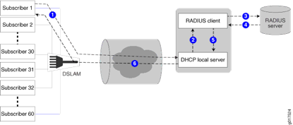
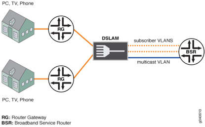
The following drawing demonstrates how the end-to-end path looks and where a BRAS/BSR is placed.

The CPE (DSL/Cable modem) is connected to the Multi-Service Access Node (MSAN), this MSAN is either a DSLAM in case of DSL networks or a CMTS in case of Cable networks. The DSLAM and CMTS devices convert the signal to Ethernet (or any other transport) and forward it to the rest of the network. This connection is then terminated on a BRAS device before it enters the rest of the network (and the internet).

The BRAS is used for 2 reasons. The first is for authenticating the client if it has the right to enter the network. Second is to enforce the subscription in terms of bandwidth limits and services that the client bought.

In the more classical model, when ATM was mostly used as transport layer, the identification of subscribers (as how clients are called on BRAS devices) where identified using PPP sessions. A client or CPE device initiates a PPP session. This ensures for encapsulation between client and BRAS and ensures some sort of circuit where you can apply authentication and enforce traffic control polices. Authentication of the client is very easy from the service provider standpoint, as a user has a username and password, which it needs to enter before getting authorized to the network. This is a little more hassle for the user as they need to know these values and have knowledge how to configure a ppp session, either on the CPE (modem) or on end-hosts.

The more modern/current approach to BRAS deployments is first of all using Ethernet as the transport layer for the usual reasons that Ethernet is very cheap and offers a lot of flexibility and now with the OAM features as 802.1ag it’s becoming very mature to use as carrier transport layer. Together with using Ethernet more flexible options become available as Ethernet utilizes the DHCP protocol for address assignments. This enables a very dynamic approach to enabling users on the network, but requires some administration by the ISP.

Traffic separation on Ethernet is ensured using IEEE 802.1Q based VLAN tags. This is done in 2 ways. Either using a single VLAN (per PoP or per service), which is called the S-VLAN model, or by using a separate VLAN for every customer (C-VLAN). In the C-VLAN model there are usually 2 tags stacked on each other as 4000 VLAN numbers is not enough for service provider scaling, so an additional tag is stacked which gives 4000×4000=16.000.000 combinations. Which should be more than enough for a single interface. This means that these models are not strictly compliant to any MEF or IEEE standard. It’s just terminology used in the BNG deployments.

The “Life of a packet” in the DHCP BRAS model:

  1.   CPE (modem / settopbox) is shipped to the client,
  2.   CPE MAC addresses are registered with back office systems of the ISP.
  3.   When installed the CPE issues a DHCP Offer message towards the network
  4. The packet is tagged with one or more VLAN (802.1Q) tags by the MSAN
  5. The tagged packet is received by the BRAS and depending on the VLAN tag combination a sub-interface (unit / IFL) is created dynamically according to pre-defined variables.
  6. In case of the S-VLAN model, there are still multiple subscribers sharing the same sub-interface, which limits the possibilities for configuration. Another sub-interface per subscriber is necessary. This will be based on the source IP address. This process is called ‘demux’ and uses the virtual demux0 interface within JUNOS. Within this process another sub-interface is created on top of the demux0 interface, which now ensures enough uniqueness.
  7. After the customer uniqueness is ensured the BRAS picks up the DHCP message and processes all possible options (within option 60 or 82, several properties can be set on which the MX can act).
  8. Next step is to send a request to the AAA server. The username that is used can be based on DHCP options or MAC address, or any custom keyword
  9. After authentication the AAA server responds with several attributes that fill in the variables of the configuration of the sub-interface.
  10. Finally a DHCP server is requested to hand out an IP address (can be local on the MX or remote through DHCP relay)
  11. Then finally everything comes together and the IP address is bound to the newly created sub-interface along with all properties as described in the profile and the variables that are sent with RADIUS attributes
  12. After the sub-interface is created the DHCP process is finalized using a DHCP Offer, Request, Accept and the client can access the network!

This was to give you a brief introduction into the BRAS functionality now with the widely deployed DHCP model. The main functionality that is now available to enable all this on the MX is the auto-configuration of sub-interfaces and the use of variables that can be filled in using RADIUS attributes.

During JUNOS 11.x releases the functionality matures and important things like GRES (supporting routing engine fail-overs) and versioning (changing profile configuration while subscribers are using that profile) became available and as of JUNOS 11.4 all major features are implemented.

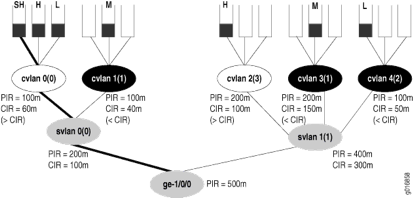
Please be aware of the platform that you choose to run the BRAS functionality on. As all the auto-configuration is performed on the routing-engine a fast RE is recommended! The new quad-core (RE-S-1800×4) routing-engine delivers blazing fast performance and enormous scaling in terms of IFLs (units / logical interfaces). When you want to deliver correct Class of Service for thousands of subscribers using a model for having various queues ensuring correct prioritization of voice/video traffic and shaping according to the bandwidth plan the customer bought you will need a feature called H-QoS (H for Hierarchical).

The per VLAN/subscriber scheduling and shaping is only available on the Q or EQ line cards on the MX platform. If you only want to use VLAN policing than you are good with a standard Trio/Cassis-based line card.

Within this model, you assume no control over the MSAN (CMTS or DSLAM), so to control the uplink bandwidth of the user you need input shapers to slow down the incoming traffic. With the Q and EQ linecards this is also possible as the queues can be distributed across both input and output traffic. To ensure correct scheduling for voice and video traffic the BRAS expects traffic to be marked with the correct DSCP and/or IP Precedence bits.

I hope you enjoyed my blog, please leave a comment if you have questions.
Fast Restoration on IP – MPLS Fast ReRoute

Service providers that have a lot of real-time traffic through their network, like mobile network operators (MNOs), are very keen on a fast restoration of service once a failure occurs in the network. In the past a lot of networks were based on SDH/SONET transport networks, which took care of sub-second (50ms) failovers. Nowadays Ethernet is THE standard for any transport within a service provider network. This introduces an issue, as Ethernet is not built for automatic failover when certain things fail.

Now there are many ways to solve this and I want to dig deeper in these technologies in several posts.  I will discuss various protocols that can solve the fast restoration requirement in different ways. Some are used in local situations (so failover to local neighbor, like a twin sibling) and others can be used in inter-site locations or can be an end-to-end protection for certain traffic.

The posts are broken down as follows:

  1. MPLS Fast ReRoute (this post)
  2. IP Loop Free Alternate
  3. BGP PIC Core/Edge
  4. Hierarchical Forwarding

Please be aware that these technologies are all related to fast restore the layer 3 forwarding path, therefore restoring the MPLS forwarding path. The MPLS forwarding path may be used for layer 2 forwarding as well. What these posts do not cover is fast restoration on layer 2 level. With the current “cloud” initiatives and next generation datacenter networks we have some extensive options for layer 2 failovers.

I can (and probably will :)) write another blog post series on those kinds of failover mechanisms.

The current blog posts are focused on the Core service provider routing to offer resilient paths through the core layer 3 or MPLS cloud in the service provider network.

MPLS Fast Reroute introduction

When MPLS was invented the first application apart from fast packet switching was creating dedicated ‘circuit-like’ connections through the network. This was done using the RSVP protocol that signals a PATH message through the network and each hop reports a label back, creating an end-to-end label switched path (LSP) according to a pre-defined path through the network.

When this initial (unidirectional) path is set-up through the network, all traffic can be send through it. Now in case of a failure we want to protect this primary path. The path is signaled with either static next-hops or the ingress node can use the IGP database to calculate the path.

Be aware that your IGP needs support for this and it needs to be a link-state protocol (OSPF or IS-IS) as then every router has a full overview of the connections in the network. I will not go in to very much detail on how RSVP works and how it utilizes the IGP database to perform a C-SPF calculation. If you want I can spend another blog about this. Just leave a comment :).

Now we have a path that we can use for our traffic we want some protection. MPLS FastReroute (or FRR) is a technique that ensures this RSVP signaled path is protected. There are a couple ways to do this.

Protection

There are three ways to protect the path:

  • Link protection
  • Node protection
  • LSP protection / end-to-end protection

It very much depends on your network topology and what you want to accomplish as far as path protection. Then there are two ways of ensuring the protection. One is a manual protection where the backup path is manually configured and signaled as an additional tunnel through the network. The second is automatic, where the router figures out which links to use for the protection and automatically signaling those paths through the network.

Why do we need it? Well the technology is introduced to ensure equal failover times as with SDH/SONET transmission networks. When using a LDP network, you need to wait for IGP convergence before the new path is ready for traffic. During tests I found out that this takes around 300-400ms when using core routing platforms (Juniper MX, Cisco ASR9k).  When using MPLS FRR you reduce this to around 50ms as the routers already have a backup path ready that should already be programmed in the relevant ASICs.

Link protection

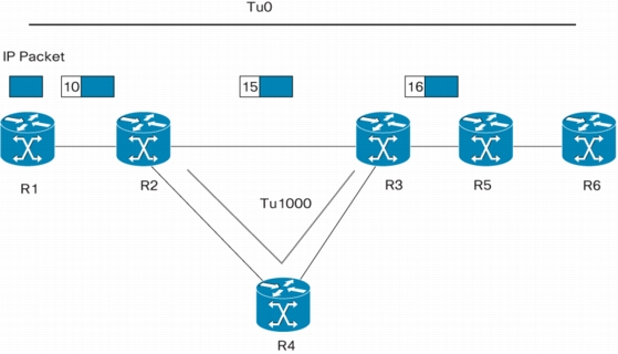
In smaller networks I usually see link protection used. For node protection you need a larger topology so this is not always possible, or when possible not very useful. Link protection is to ensure all links are secured using a backup path as the following drawing illustrates:

The primary tunnel follows the path R1-R2-R3-R5-R6 using MPLS labels according to the drawing. When the link between R2 and R3 fails a backup tunnel is signaled by R2 to R3, around the protected link. When the link breaks R2 pushes an additional label on top of the label stack and sends it to R4. Then R4 will pop off this label (PHP behavior) and R3 will see the standard label 15 as it usually expects.

Node protection (or link-node-protection)

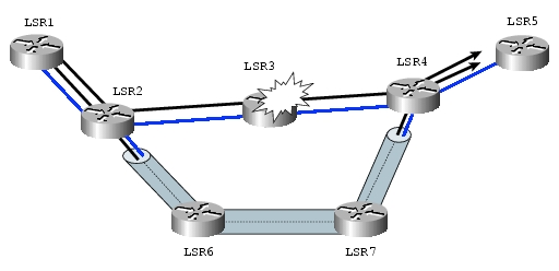
Node protection is used in larger environments to protect the link and the node in case of failures. As the name already says, this is the same technology as link protection, but then the backup path is signaled completely around the node, instead of just the link. As you can see in the previous example R3 is still used in transit and just it’s link to R2 is protected. In the following drawing you can see that LSR3 is fully protected as the backup path terminates on LSR4.

LSP / end-to-end protection

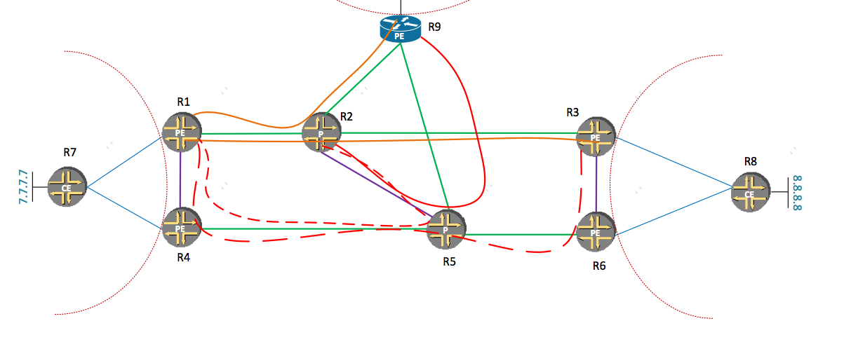
From what I’ve seen, Juniper is the only one that actually implements this. I’m sure it’s possible on Cisco as well, but when configuring the ‘fast-reroute’ command on a LSP it will signal a backup path through the network fully excluding any node/link that the primary path travels through. This sound pretty rigorous and it is J, but it makes sense in a square based (ladder) design as seen in the drawing below

The orange path from R1 to R3 is the primary tunnel and the red-large-dashed tunnel from R1 through R4, R5 and R6 is the back-up path that Juniper routers automatically signal when fast-reroute is enabled.

In smaller topologies with just a couple PE’s, this is do-able, but when your topology grows you require a backup path for every LSP and that can be hundreds or thousands in the larger deployments, making it very difficult to troubleshoot.

The other protections like link and node protection create a backup path around a specific link or node and all LSP’s that travel through those routers can use the same backup path in case of failures.

So when you have a specific case where you want end-to-end protection of your LSP, this is the way to go, but under normal circumstances I would recommend using link or node protection, which scales much better!

Interoperability

Now vendor interoperability is very important when it comes to Fast Rerouting. In the beginning when this was developed there were several drafts published that all used different objects in RSVP (DETOUR, BYPASS, etc.). Therefore some people might tell you that Cisco and Juniper FRR doesn’t work together.

This is long gone! But you have to configure it correctly. Like I already said, when you configure fast-reroute on a Cisco LSP it means it will use a backup tunnel when it’s available (manually configured). You require additional commands for creating the backups automatically (auto-tunnel), where you also configure whether you want link or node protection.

When you configure fast-reroute under a Juniper LSP it will signal a end-to-end protected path, which might not be what you want. You need to configure link or node-link protection under the Juniper LSP to advertise the desired protection. Then RSVP needs to be configured on each router to support either link and/or node-protection by enabling this under the interfaces configured in RSVP.

When configured correctly they perfectly interoperate!

RFC 4090 (http://tools.ietf.org/html/rfc4090) defines the finalized Fast Reroute standard, which is based on a draft by Avici. All vendors implemented this RFC and like I said, when configured with the correct commands, you can let them interoperate perfectly with each other.

Configuration

Below are some configuration examples. The first is a example of a Cisco IOS router. You see a tunnel configured and auto-tunnel being enabled to signal the backup path automatically for link-protection. Keep in mind that the backup tunnel needs to be configured on every node that you want link protection on. The ‘n-hop’ command configured ensures the link-protection, when ‘nnhop’ would be configured it would mean node-protection.

mpls traffic-eng auto-tunnel backup nhop-only 
interface Tunnel1
 ip unnumbered loopback0
 tunnel destination x.x.x.x
 tunnel mode mpls traffic-eng
 tunnel mpls traffic-eng path-option 1 dynamic
 tunnel mpls traffic-eng fast-reroute

The following example is for Juniper JUNOS routers. You see the same type of protection configured including the automatic protection for links. This is done using the link-protection command under the RSVP protocol. Additionally the same command needs to be configured under the LSP configuration.

[edit protocols]
mpls {
      label-switched-path lsp-name {
            to x.x.x.x;
            link-protection;
      }
}
rsvp {
      interface interface-name {
            link-protection;
      }
}


Summary

I hope I was able to give you a quick and brief overview of the different ways of protection for traffic engineering tunnels in MPLS networks. This was only one way of protecting traffic. Currently this is the most commonly used technology by service providers in the world, but others are rising that don’t require so much configuration, but do require tuning and sometimes specific network designs.

Stay tuned for the next blogpost about IP Loop Free Alternate!

Rick

© 2024 Rick Mur

Theme by Anders NorenUp ↑