After discussing the issue I’m running into in my home lab set-up in the previous post. This post will outline configuration and some final testing to confirm a succesful workaround.
The issue as outlined in the previous post is a combination of having a GRE tunnel that is not the same as the destination IP of the IPsec VPN. So the policy engine has trouble understanding the double encapsulation in ESP packets first and in the GRE tunnel second. As shown in the packet capture, the ESP encapsulation is not performed and packets are sent over the GRE tunnel unencrypted (a behavior of GRE over IPsec, which is a much more ‘normal’ use case for this).
My solutions should ensure that the GRE tunnel is not seen as the next-hop, so the SRX has a chance to encrypt the traffic first.
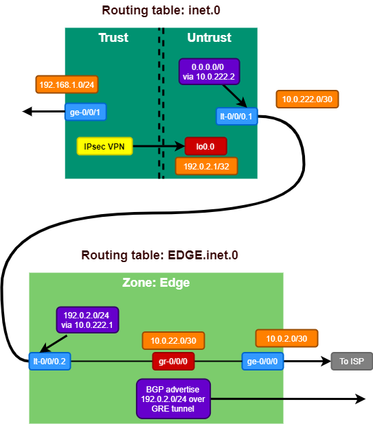
The goal of the solution is to build a set-up like the diagram below. Where the inet.0 routing table, where the IPsec VPN resides, does not contain the GRE tunnel to connect to the Colo router.
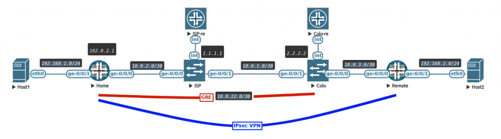
The set-up is still the same where 2 vSRX firewalls connect over 2 vMX routers to each other with a policy based IPsec VPN. This detail is important as the behavior of not encrypting packets is not seen when deploying a route based VPN (with st0 interface).
Virtual Router
To separate some traffic from the rest, we need to create another routing table inside the system. Junos calls this concept a routing-instance, which can be many things. One of them is a virtual router instance type, which is similar to the VRF-lite concept on Cisco platforms.
Let’s first setup this virtual router instance and move the GRE interface and relevant BGP configuration to it.
routing-instances {
    EDGE {
        routing-options {
            static {
                route 2.2.2.2/32 next-hop 10.0.2.1;
            }
        }
        protocols {
            bgp {
                group COLO {
                    type external;
                    export colo-export;
                    peer-as 65000;
                    neighbor 10.0.22.1;
                }
            }
        }
        interface ge-0/0/0.0;
        interface gr-0/0/0.0;
        instance-type virtual-router;
    }
}
The physical WAN interface and the GRE interface are now moved into the routing-instance and the BGP session will now be set-up.
Keep in mind that the security policy and zoning configuration should be adjusted to this new set-up to allow traffic to flow between the interfaces in the virtual-router (from zone X to zone X policy).
The second step is to allow traffic to go from the newly created virtual-router to the default global routing table (inet.0). With route leaking the next-hop would not change, so we need something else. The best tool to solve this is a logical-tunnel interface.
Logical tunnels
The concept of logical tunnel interfaces has been around for a long time. I heavily used them to connect many logical-systems (early version of slicing in routers) on a MX480 together to build out a JNCIE lab setup with only 1 physical MX.
Technically the logical tunnel interface is a loopback functionality inside the system to simulate a hairpin link without having to use physical ports. The logical tunnel works by defining 2 units. These units can each be placed in separate VRF’s, Logical Systems, etc. to bring traffic between these segmented areas and is treated just like any other phyiscal interface.
On platforms with PFE’s (Packet Forwarding Engines), the looping of the traffic is done in hardware. On Trio based MPC linecards this requires enabling of tunnel-services as this will consume bandwidth (this is also the case to enable GRE tunneling).
More details found in the official Juniper documentation
In case of the vSRX and also the smaller physical SRX platforms, the system uses dedicated CPU cores as data-plane where the logical tunnel traffic is handled.
Let’s setup the logical tunnel to allow traffic between the virtual-router and the global table configuration.
interfaces {
    /* Loopback VR to Global */
    lt-0/0/0 {
        unit 1 {
            encapsulation ethernet;
            peer-unit 2;
            family inet {
                address 10.0.222.2/30;
            }
        }
        unit 2 {
            encapsulation ethernet;
            peer-unit 1;
            family inet {
                address 10.0.222.1/30;
            }
        }
    }
}
routing-instances {
    EDGE {
        routing-options {
            static {
                route 192.0.2.0/24 next-hop 10.0.222.2;
            }
        }
        interface lt-0/0/0.2;
    }
}
routing-options {
    static {
        route 0.0.0.0/0 next-hop 10.0.222.1;
    }
}
As seen in the configuration. The logical tunnel interface has unit 1 and unit 2. They are connected to each other using the ‘peer-unit’ command. Unit 1 is then connected to the virtual router and unit 2 ends up in inet.0.
As the BGP session is now moved to the virtual-router, we need to make sure that all traffic is going towards the virtual router using a static default route. Then secondly it’s necessary to ensure the traffic towards the public IP prefix is received in inet.0 so another static route for 192.0.2.0/24 is required in the virtual-router to be sent across the logical tunnel towards inet.0
This results in the following routing tables.
root@Home> show route | no-more

inet.0: 6 destinations, 6 routes (6 active, 0 holddown, 0 hidden)
+ = Active Route, - = Last Active, * = Both

0.0.0.0/0          *[Static/5] 00:10:58
                    >  to 10.0.222.1 via lt-0/0/0.1
10.0.222.0/30      *[Direct/0] 00:10:58
                    >  via lt-0/0/0.2
10.0.222.2/32      *[Local/0] 00:10:58
                       Local via lt-0/0/0.2
192.0.2.1/32       *[Direct/0] 02:20:32
                    >  via lo0.0
192.168.1.0/24     *[Direct/0] 02:19:46
                    >  via ge-0/0/1.0
192.168.1.1/32     *[Local/0] 02:19:46
                       Local via ge-0/0/1.0

EDGE.inet.0: 9 destinations, 9 routes (9 active, 0 holddown, 0 hidden)
+ = Active Route, - = Last Active, * = Both

0.0.0.0/0          *[BGP/170] 00:06:37, localpref 100
                      AS path: 65000 I, validation-state: unverified
                    >  to 10.0.22.1 via gr-0/0/0.0
2.2.2.2/32         *[Static/5] 00:10:58
                    >  to 10.0.2.1 via ge-0/0/0.0
10.0.2.0/30        *[Direct/0] 00:10:58
                    >  via ge-0/0/0.0
10.0.2.2/32        *[Local/0] 00:10:58
                       Local via ge-0/0/0.0
10.0.22.0/30       *[Direct/0] 00:06:39
                    >  via gr-0/0/0.0
10.0.22.2/32       *[Local/0] 00:06:39
                       Local via gr-0/0/0.0
10.0.222.0/30      *[Direct/0] 00:10:58
                    >  via lt-0/0/0.1
10.0.222.1/32      *[Local/0] 00:10:58
                       Local via lt-0/0/0.1
192.0.2.0/24       *[Static/5] 00:10:58
                    >  to 10.0.222.2 via lt-0/0/0.2
We see pretty much the same routing table as in the previous post, with only the addition of 10.0.222.0/30 as transit subnet on the logical tunnel and now being separated into 2 separate tables.
Verification
Now let’s see if we can finally reach host2 from host1 as that did not work in the previous post.
host1:/# ping 192.168.2.2
PING 192.168.2.2 (192.168.2.2) 56(84) bytes of data.
64 bytes from 192.168.2.2: icmp_seq=1 ttl=62 time=4.46 ms
64 bytes from 192.168.2.2: icmp_seq=2 ttl=62 time=3.42 ms
64 bytes from 192.168.2.2: icmp_seq=3 ttl=62 time=3.20 ms
64 bytes from 192.168.2.2: icmp_seq=4 ttl=62 time=2.67 ms
64 bytes from 192.168.2.2: icmp_seq=5 ttl=62 time=3.21 ms
64 bytes from 192.168.2.2: icmp_seq=6 ttl=62 time=2.85 ms
64 bytes from 192.168.2.2: icmp_seq=7 ttl=62 time=2.93 ms
64 bytes from 192.168.2.2: icmp_seq=8 ttl=62 time=3.14 ms
64 bytes from 192.168.2.2: icmp_seq=9 ttl=62 time=3.28 ms
64 bytes from 192.168.2.2: icmp_seq=10 ttl=62 time=2.50 ms
^C
--- 192.168.2.2 ping statistics ---
10 packets transmitted, 10 received, 0% packet loss, time 9013ms
rtt min/avg/max/mdev = 2.501/3.166/4.459/0.509 ms
host1:/#
Finally! Let’s check if the packet capture also shows the same expected result.
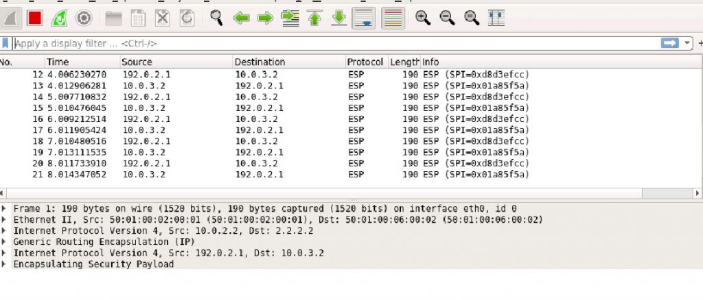
With the ESP packets showing correctly when monitoring the ge-0/0/0 WAN interface on the Home vSRX. We can confirm that the workaround works!
Conclusion
This solution seems a bit far fetched, but it does work quite well for my use case at home. I have not had any stability issues and am very happy with it. Still this is quite a complex set-up to troubleshoot so please prevent deploying things like this in production, but if you do run into this corner case of having to use policy based VPNs on a vSRX with a GRE tunnel as underlay. You know how to solve it!

Leave a Reply