Limitless Networking

Category: Home lab (Page 1 of 3)

JNCIE-DC lab in EVE-NG tips and tricks

After having some feedback regarding my previous post on running the JNCIE-DC self-study workbook in EVE-NG. I wanted to share some of the most common questions I personally experienced while using the lab and general things to be aware of and some tips!

I also ran into some aspects of going through the workbook that also would change some small decisions I made when deploying the lab.

vQFX version

The more recent versions of the vQFX are experiencing some issues inside EVE-NG. Sometimes the vQFX RE comes up in the line card role. This is an aspect of Virtual Chassis technology, which is not supported on the vQFX. When the system is in line card role, it means it does not maintain an editable configuration as that would be done by switches in the VC with Routing Engine role.

I am currently running vQFX with Junos 17.4R1.16 and that is very stable at the moment. In the JNCIE-DC lab environment a much older version is used, so for feature parity is not an issue and stability matters most right now. So stay away from the more recent Junos 18.x and Junos 19.x vQFX versions to ensure a stable device. I have gotten them to work plenty of times, but it’s not stable enough and I don’t want the lab to be in my way when I’m studying for an exam.

vQFX data-plane / em1 interface

The vQFX is supported to run in 2 different versions. ‘light’ mode and ‘full’ mode. Light mode means that you only boot up a routing-engine image. This deployment will only support any layer 3 IP services to, for example, test IP Fabric use cases. Your interfaces will all map to ’emX’ ones and will not be shown as xe-0/0/X in the system. To utilise the virtual PFE, the full potential of the vQFX and the ability to run layer 2 bridging and EVPN services you will need the ‘full’ version which requires to deploy a second VM for each vQFX which will run a virtualised version of the Q5 PFE.

It’s key to have the connection in place between the vRE and vPFE. This is done by making a connection on port em1 on the vRE and port int on the vPFE. On the vMX the connection is similar, but once made in EVE-NG the configuration is not visible in Junos. On the vQFX the IP addressing between these 2 VMs is required to be in the configuration, otherwise you will lose the connectivity to the vPFE and that will result in losing the xe-0/0/X interfaces being visible from the CLI.

It’s easy to miss this out, because the vQFX boots up with a full list of interfaces with regular ethernet-switching configuration. During your labbing it’s easiest to delete the entire interface stanza before starting, but by doing this you will also delete the em1 interface which handles this vRE to vPFE communication and needs to be configured with the IP address 169.254.0.2/24. The em0 interface is similar to the fxp0 interface on vMX and that is your direct connection to the virtual RE or the out of band management interface.

When I start working on a new vQFX I immediately delete all interfaces, but make sure you put the em1 configuration back! Along with maybe your management subnet configuration!

delete interfaces

set interfaces em1 unit 0 family inet address 169.254.0.2/24

Management subnet

The JNCIE-DC workbooks consists of many chapters and many parts within those chapters. For each part in a chapter there are separate starting/initial configurations as they typically do not build on top of each other. This means you will be loading a lot of new configurations during your labbing.

Copying and pasting configurations over the virtual console connection that EVE-NG sets up to the serial port is typically not the best idea. Unless you delay the speed that your terminal emulator pastes information in the window.

To also get the best connection to your devices. I would recommend using the out of band management interfaces (em0 on vQFX and fxp0 on vMX) to connect to the devices. It gives me the most stable connection to the devices and does not mind pasting in big chunks of configuration.

The initial configurations of the JNCIE-DC workbook are set-up with an out of band management subnet of 10.10.20.0/24. I’m using a different subnet for my lab devices VLAN, so when I open a new initial configuration I have to do a find-replace action. You could also make your life easier by using the subnet in our lab if that’s an option!

The SSH access to the devices is really helpful again to quickly load configurations, which I not only use for the initial configs, but also for copying and pasting parts of config between devices during the labs.

Initial configurations

Take good care of loading initial configs for each part. EVE-NG is not the best at managing this on Juniper devices, because it expects a device to be logged in. Which a Juniper device never is. You always end up in a log-in prompt.

I found it too much of a hassle to work on updating the configs, as each chapter has multiple initial configs for the various parts of the chapter. This means you will be loading and replacing a lot of configurations during your work in the book.

I find it useful to save my final configs for each part as well. Some people like to log all the command outputs to a text file, but I feel that’s a bit much when you’re working on a lot of devices and are typing a lot. Saving final configs does help in checking your answers in the book at a later time. I typically work on it in the evening and then only have time to finish a few parts of a chapter. The next day I’ll go back and verify my work in the book and review my configs in text files.

When loading in the initial configurations. It’s important to keep in mind your management subnet on the fxp0 and em0 interfaces, so that you don’t lose connectivity after a commit!

Loading in a brand new configuration on a Junos device is fortunately very easy. Just use the load override terminal command and paste in your new config. After a commit your device has a complete new identity!

Copy/Paste between devices

When working through the chapters. You will find that a lot of configuration will be similar on multiple devices. Especially routing protocol knobs such as authentication or policies. I find it very useful to do configuration on one device and then using a show | compare to verify. Copying the output of that to a new device works really well by using the load patch terminal on the other device to load in the differences.

I also find it very useful to have a text editor open next to me. I use Sublime Text 3 with the Junos plugin so it highlights the syntax. Especially configuring a lot of BGP peers (like in an IP fabric setup), it helps keeping the configuration consistent and only a few IP addresses will change between devices. Being able to quickly change this and then copying it over to the other device saves a lot of time and potential errors!

Reconfigurations

As mentioned before, the parts within the chapter do not build on each other. This means you have to wipe and reconfigure the devices before moving to another part of the workbook. I’ve experienced a few times that after I wiped the config and reconfigured the device for the next part (load override) that the devices can behave strange. Which would result in not having IP connectivity on links. The problem is that you will be configuring something and you want to verify that what you did is correct. So if verification fails, it makes you doubt your own config. In the case of reconfiguring the devices multiple times, I’ve seen it happen that sometimes the config is not correctly applied in the vPFEs. This means that the configuration does not reflect the actual implementation in the device. To get this fixed a full reboot of both the vRE and vPFE would solve this!

Flapping peers

Again similar to the previous point. I reset the configurations to a new part of the chapter and after verifying IP connectivity I thought everything was OK, but after configuring BGP. I experienced weird issues with flapping peers. Every 1 to 2 minutes all my BGP peers would suddenly reset. Even after a reboot of the virtual appliances!

I abandoned troubleshooting initially, because it was already late at night. I powered off my server and powered it back on again the next day. After the appliances were all running again. The problem was gone and my config hadn’t changed at all! So even if a reboot doesn’t fix your issue try to close the lab and re-open it in EVE-NG or reboot your entire server to fix issues of which you are (almost) certain they are not related to your configs!

EVE-NG Client Pack

As a few final thoughts I’d like to highlight some of the excellent features that EVE-NG brings to the table. The first I’d like to mention is the client pack that EVE-NG offers for all desktop operating systems. Logging in on the native console (not the HTML5 one, which I only use when I’m not connected of EVE-NG offers you the ability to open console sessions to your devices using your favorite terminal emulator. Which to me personally is iTerm2 on macOS and SecureCRT on Windows.

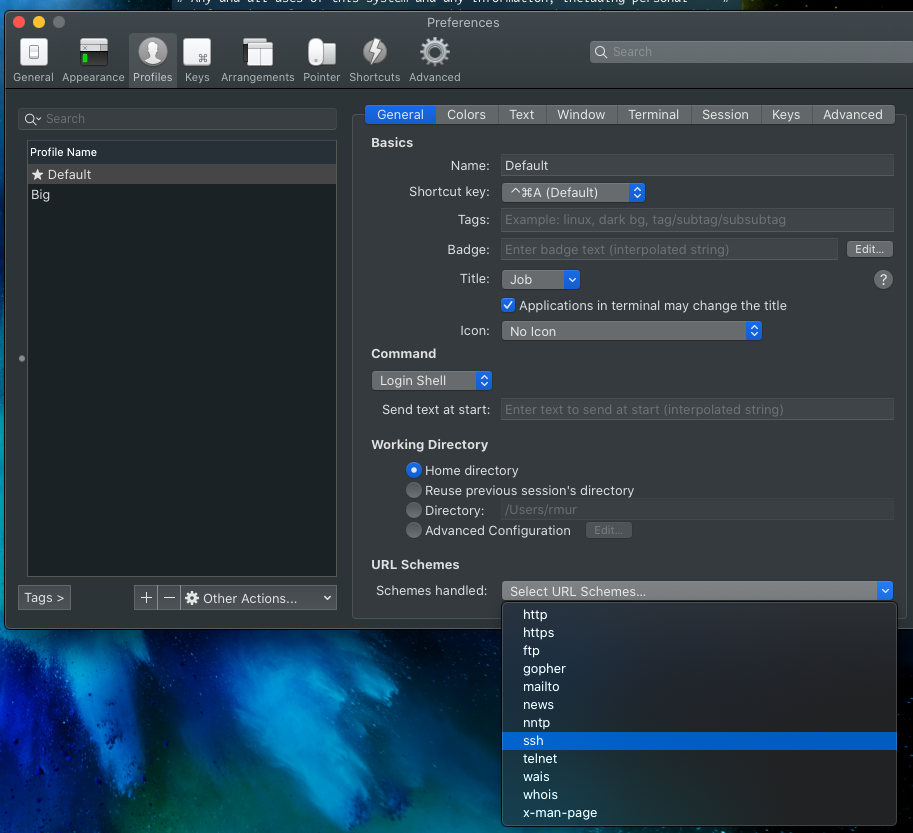
On iTerm2 ensure you select the setting to have iTerm2 be the default ssh:// url handler in the profile settings.

On Windows if you want SecureCRT to be used as default app to open console windows. The EVE-NG Client Pack installs scripts to make this easy. Go to C:\Program Files (x86)\EVE-NG\ and open the .reg file that reflects either the 32-bit or 64-bit version of SecureCRT which is abbreviated with sCRT. After running the reg file, SecureCRT should open automatically when opening console windows. If it does not search in your start menu for Default Apps, then go to Choose default apps by protocol and select SecureCRT as the default application for the TELNET protocol.

By default on Windows each session you open on EVE-NG will open a new window of SecureCRT. Where most people will prefer new tabs. To change this go into your SecureCRT config directory which is usually found under: C:\Users\<username>\AppData\Roaming\VanDyke\Config and find the Global.ini file and change the following line:

D:"Single Instance"=00000000

and update to

D:"Single Instance"=00000001

Now all new windows will open as tabs in the same window.

EVE-NG Miscellaneous

Depending on your server the bootup times it could take a very long time to boot all the virtual appliances. Sometimes it could feel that they are stuck, but be patient is the only solution to that (or faster CPU’s of course πŸ™‚

Finally, make sure you update your EVE-NG installation using standard apt commands. Recently a vulnerability was discovered in one of the modules that EVE-NG uses so always make sure you are running an up to date installation. Fortunately that’s very easy to do!

Happy labbing!!

Home Network 2020

Recently I moved to a new house and as a lot of reconstruction was done to bring the house up to date. I took the opportunity to have something I’ve always wanted in my home: a server rack! In my previous lab set-ups they were either located in my employers lab location or placed in a storage space. Now I had the opportunity to really make something nice for myself.

The rack contains both the equipment for running the automation and infrastructure in the house and my home lab. In this post I’d like to show some details of the equipment in it and the basic infrastructure that is running on it.

Location

On top of my garage is an attic that exactly fits a 15RU rack. As my home office is built right below it I had to take care of sound levels, so no high-rpm 40mm fans.

After taking away the top and bottom of the rack it could fit exactly! All Cat.6 cabling is terminating on Panduit patch panels and all wall outlets are nicely numbered. I can say that if a device has a UTP port, it is connected! I had the luck that we were doing a complete overhaul of the wiring in the house, so I could put UTP wall outlets anywhere I wanted to. Overall there are 41 Cat.6 UTP connections in the walls and outside on the house.

I’m actually quite proud of the result!

Patch panels

To connect all house wiring I use 2 Panduit 24 port keystone panels to house all the cables. Cabling used is standard Cat. 6. In total about 1200 meters of UTP cabling went into the house!

Keystone connectors: Panduit CJ688TGBL

Panels: Panduit CP24BLY

Switching

The switching infrastructure of course had to be based on Juniper EX switches. I did look at a Ubiquity Unifi Switch Gen 2, but didn’t chose it because the amount of PoE ports on the non-Pro models are a bit low (16) and I already needed 14 PoE ports, so with the Unifi only having 16 PoE ports, that didn’t really give room to grow. To get a full PoE model I had to go for the Pro version which is rather expensive.

Since I already owned a Juniper EX2300-24T from a project a couple years back it was relatively easy to scout eBay for a good price and get a PoE version. Which would allow me to combine the switches in a Virtual Chassis. Eventually I even found a barely used Juniper EX2300-48P for a decent price. With the 48-port model I could wire up all ports in the house to the switch and even support PoE on all those ports. Which already came in very useful when I was testing some access points in the living room and could just connect to any outlet! Wiring up all the ports also gave me the option to use the outlet number as switchport number, so I can always easily remember which port goes to which outlet. (Which also explains why the cabling run from the patch panel onto the switch may look a bit odd at first).

To configure the EX2300 switches in Virtual Chassis, you have to use the on-board 10Gbps SFP+ ports. I picked up a couple of SFP+ DAC cables to connect the switches back-to-back and also connect some other SFP+ ports that I have in the rack.

After powering up the EX2300-48P for the first time I noticed some whining of the fans that I could hear from below it in the office. I bought a couple of Noctua NF-A4x20 PWM fans to replace the default fans with. This Reddit post has good instructions on how to do the wiring on the Noctua’s as the coloring is a bit different from the default ones. After swapping them out, temperatures are pretty much the same and fan noise is completely gone!

Switching: Juniper EX2300-48P and EX2300-24T in Virtual Chassis

Fans: Noctua NF-A4x20

Internet / Routing

The routing part of the network is still under construction as I purchased a Juniper SRX300 to be the WAN router handling the Internet traffic and connecting the public IP subnet to the Internet like I explained in my previous post.

As Internet connection I currently have a KPN Bonded-DSL connection getting me speeds up to 185Mbps down and 63Mbps up. Unfortunately the area I moved to does not have any fiber-to-the-home and as it’s a super small village, I don’t expect it coming here anytime soon. Recently the cable provider Ziggo upgraded the network to support 1Gbps down and 50Mbps up, but I have to admit the 185Mbps down is more than enough for 99% of the time and I do like the pretty-much static IPv4 address and native IPv6 they provide (which Ziggo doesn’t support in my area at this time).

As the Juniper SRX300 does not have any PIM slots, there is no way I can connect the DSL signal natively to the SRX. I could have gone for a SRX320 that does support additional slots, but unfortunately the DSL PIM does not support DSL bonding which I needed to run my connection at full speed. Therefore I opted to pick up a FritzBox 7581 DSL modem that I configured in full-bridge mode. This means that the modem basically translates the DSL to Ethernet and does not set-up any connection by itself. This ensures I can set-up a PPPoE session on my SRX300 and terminate the IPv4 and IPv6 addresses natively on the SRX, without having to go through some double-NAT set-up.

Now since KPN is also my TV provider I receive the live TV signal over multicast in another VLAN. I have not taken the time to set this up on the SRX as the signal is received with a TTL of 1, so running PIM on the SRX is not an option and IGMP Proxy is not supported, there is an alternative that could work, but I still have to test that out (and request a maintenance window, as the network is in production ;).

Because I have not figured out the multicast set-up on the SRX yet, I’m using the old router I used in my previous home set-up, which is the Ubiquiti USG. It performs quite well and after figuring out the PPPoE, Multicast and IPv6 set-up it’s very stable. I picked up a rackmount for it, so it looks nice in the rack! I’ll be sure to cover the configuration of the SRX when it’s finished, as I haven’t been able to find running a KPN IPTV set-up over a Juniper SRX yet. For the USG I used some parts of this configuration.

Modem (bridged): FritzBox 7581

Router and Firewall: Juniper SRX300 / Ubiquiti USG

Wireless

For wireless connectivity I’m using the same set-up I’ve been using for a few years now. I really enjoy working with the Ubiquiti Unifi line of products and they have proven to be really stable and performing well.

In the livingroom I have placed one Unifi UAP-AC-HD centrally in the room. I initially planned on adding one on the second floor (first floor for Europeans πŸ˜‰ ), but the AP has a great range so even in bed I still get full performance from the access point.

In my office I needed a second UAP-AC-HD, as it is too far away from the livingroom and I wanted to have full Wi-Fi coverage and speed when I’m working.

The third and fourth access points are Unifi AP-AC-PRO, they are covering my front- and backyard and are placed outside on the house. They are water resistant, although they are quite out in the open now, so I have to wait and see how long they last in full rain and winter season.

Wireless: 2x Unifi UAP-AC-HD and 2x Unifi AP-AC-PRO

Home Automation

For automating lights and heating in the house I use a number of appliances. I won’t focus too much on the details here as that would be enough for a separte post. I use a combination of systems and I’m still working on combining everything together in Home Assistant at some point.

Currently I use a number of Philips Hue lights, so a Hue Bridge v2 is connected to the network.

Next I use quite some Z-Wave based appliances, like dimmers, switches and heating equipment. To control that I currently use a Fibaro HomeCenter 2. As more devices are WiFi based, I may move all Z-wave appliances over to Home Assistant at some point, but the Fibaro solution has served me well for a number of years. Fortunately the antenna is strong enough that it can reach throughout the entire house from the server room. Recently Fibaro released HomeCenter 3 which has some advantages over my version, but not enough to justify an upgrade.

Next I use a Eufy Video Doorbell. I used to have an original Ring, right after they rebranded from DoorBot, but that got broken during the move and I really liked the aspect of Eufy having a local storage solution connected to the network, rather than paying a fee for a cloud recording option for Ring. I’m happy I made the switch and really like th quality of the Eufy!

Finally I monitor the power usage in my house by connecting to the P1 port on my ‘Smart meter’. Fortunately the Dutch government mandated an open interface on every smart meter installed in houses. I use the great project DSMR Reader to monitor power usage over time running on an Upboard that I had laying around.

Home automation:

UPS

Since I’m running critical infrastructure in this house since working from home, I needed something to keep my Internet connection up and running all the time. Especially since the power grid in the village I live in now is not as good as my previous houses, there are slight glitches from time to time, enough to reboot equipment, so I opted to get a decent UPS. I tried to get one not too big for the environment as I don’t need a 2 hour battery time, but I’d like to be able to survive a dip in power for at least an hour. I opted to get an APC UPS of 1000VA capacity. The version I chose has a very simple integration on the network called APC Smart Connect, as I didn’t want to pay for the way overpriced network module that APC sells in their more enterprise focused products. The SmartConnect tools simply e-mails me when something happens to the UPS, like when it kicked in the battery power or when it needs a software upgrade. More than enough for my use case at home!

As my DSL modem is not in the server rack, but close to where the phone line is entering the house, I also use a small APC UPS to ensure my modem stays online as well.

UPS: APC SMT1000RMI2UC

NAS

I’ve been a big fan of Synology products for many years, I have owned a Synology NAS since 2007 and have gone through a few models. As this is my first ever home rack, I could finally upgrade to a RackStation! Now as Synology is releasing new products throughout the year it’s always hard to figure out if the model you picked is going to be replaced by the next upgrade cycle, but it is what it is.

I was using a Synology DS1518+, which is quite a recent model and I’m using this now as a backup NAS in a remote location. I upgraded to a model that was released in the same year. As I wanted some room to grow and expand capacity without replacing all my disks I wanted more slots in the most efficient rackspace.

The model I went for is the Synology RS2418+ which has a quad core Intel Atom C3538 (not vulnerable to the issue with C2k series) and DDR4 memory. I went for 16GB, as that fulfils more than I need on it as I’m not looking for the NAS to become a full server. I want it to host files, have blazing fast file transfers and maybe run a few containers. The RackStation is released in the same year as the NAS I’m upgrading from, but the CPU is quite a bit faster plus it is using DDR4.

I moved the disks from my old NAS over and upgraded the volumes a bit by adding disks. I currently run the following volumes:

  • 5 x 8TB WD Red in Synology Hybrid Raid 1 with BTRFS with a usable capacity of 28TB as main data volume
  • 4 x 480GB Intel SSD DC S3520Β in RAID 0 with BTRFS with a usable capacity of 1.7TB as volume to store Virtual Machines accessible via NFS

With 9 slots filled, this leaves me with 3 empty slots for future capacity. My main storage volume is about 40% filled so that should be fine for quite some time!

For hosting virtual machines I use a RAID 0 volume as I just want fast SSD based storage and I don’t really care about high availability, because all VMs are backed up on the main data volume, so in case of an SSD failure a restore is easily done.

NAS: Synology RS2418+

Disks: WD Red 8TB (watch out for SMR disks at lower capacities, as they can give you a bad performance in a NAS setup)

SSD: Intel 480GB (look for $60-90 ones on eBay)

Server 1: NUC

The first server that I run 24×7 is an Intel NUC10i7FNK with 64GB RAM and no storage. The NUC is a perfect form factor to host just a few virtual machines with a modest power consumption. I run VMware ESXi 7 on the NUC. Please read the blogs on installing ESXi on this NUC carefully as you will run into issues otherwise.

ESXi has the SSD volume of the NAS mounted via NFS. The virtual machines and containers running on this server (yes I run Docker in a VM) are meant to stay online all the time. This basically means that it runs services that are used in the house like monitoring my house power usage, Adguard Home, Home Assistant and NetBox.

Server 1: Intel NUC10i7FNK, 64GB RAM

Server 2: Dell R730

The real powerhouse of the home network is my Dell R730. I wanted to have a beefy server to run virtual network topologies and other experiments on. The server is also not meant to run 24×7 so I don’t really mind power usage too much as the system only runs a few hours a day when needed. I did take a look at hosted options in various cloud offerings, but when renting a decent performant server for a number of months I could also scout eBay and the Dutch classifieds version: marktplaats.nl.

I have been using a Dell R610 for many years with 8 Nehalem cores and 48GB memory, but as I was building out topologies with a number of vMX and vQFX devices it was taking far too long to get everything booted up and as that system was getting 10 years old. I figured it was time to get it replaced.

After looking for various options, I knew I wanted a high core count (because those virtual network appliances consume a lot of CPU power) and a decent amount of memory. Preferably a recent CPU architecture as modern cores are so much more performant than older and more power hungry CPU’s. Which is why I narrowed it down to at least having DDR4 memory, as that brings the selection down to more recent models of servers. Unfortunately these are considerably more expensive than older CPU’s with DDR3 memory.

After searching for quite some time I stumbled upon a guy offering 2 Dell R730 servers with 256GB DDR4 memory each! Unfortunately only 2 CPU’s came with the servers so I guess one server was bought as spare unit or they disappeared for another reason. I agreed on a very good price for both of the servers. The memory itself could have gone for almost the price I paid in total. So because the deal was so good I opted to buy both and get 2 CPU’s separately to drive the second server.

One of the servers is now in a colocation hosting a number of servers like a Unifi Controller (I host all Unifi setups in my family) and some other services I host. This server came with 2 Intel Xeon E5-2670v3 12-core CPU’s and 256GB of memory and I’m very happy with it!

The server I run at home I had to buy new CPU’s for as it came with empty sockets. As the 8 core machine I had was very underperforming I wanted to get the maximum core count I could get, so I ultimately found a compatible pair of Intel Xeon E5-2699v3 18-core CPU’s giving me a total of 36 cores and 72 threads to work with. Now after a couple of months using them, I understand this is way overkill for a home lab, as I haven’t been able to stress it beyond the 40% CPU with quite decent lab topologies. Unfortunately 1 memory stick is broken, but I don’t need that much memory anyway. I could have easily settled for 96/128GB as well.

The version of the chassis I have is using 3,5″ drive bays without any disks, so I picked up some more Intel 480GB SSDs that I also run in my NAS and some disk brackets with 2,5″ adapters as I wanted to install Ubuntu and EVE-NG bare metal on this system. The system even has a 10Gbps NIC on-board, so the server is connected with 10GE using DAC cables to my EX2300 VC, which nicely fills up a few 10GE ports on the switch!

As the power usage of the Dell server is much higher and I don’t need it to run all the time I wanted to have the server off when I’m not using it. Unfortunately I’m locked out of the iDRAC console by a password that the previous owner also doesn’t know and since the iDRAC module on this particular server comes embedded on the motherboard I would need to replace the motherboard to get access again. That’s why I opted to use a much simpler solution/workaround for turning the server on and off remotely. I enabled Wake on LAN on the port I use to manage the system and with a very simple command I can wake the server remotely from another system in the network. This works quite well and saves me a lot of power usage in a year!

Server 2: Dell R730, Dual Intel Xeon E5-2699v3 18-core CPU, 256GB DDR4 RAM, 2x 480GB Intel SSD in RAID-1 to run the OS

OS: Ubuntu with EVE-NG Pro

EVE-NG

As mentioned I run EVE-NG Pro bare-metal on the Dell R730 server. I really enjoy working with EVE-NG as it’s so easy to use and offers everything I need to to quickly spin up a virtual lab and can drag and drop connections to any virtual appliance I want. Of course the main appliances I run are:

Then to have some hosts connected to the networks, I’m using a simple container that has a number of network tools pre-installed. Using a startup-config these are given IP addresses.

I can highly recommend using EVE-NG for any of your network virtualization topology needs as I’ve thrown together rather complex topologies during calls with a customer and could go in demonstrating something very easily!

The Pro version is not really necessary, as the free version already comes with most of the features, but it does give you some useful tools like support for Docker containers and adding/removing connections while the appliances are running. Additionally you support a great product for a minimal yearly fee!

Conclusion

This all seems a bit overkill for running in your own house and especially since most of this could easily run in the cloud, but as an engineer I just love setting this stuff up and I enjoy it every day. I truly enjoy having this in my house and I’m actually kind of proud of it!

If you have any questions or thoughts or want to share your own home network rack, don’t hesitate to leave a reply in the comments or reach out on Twitter!

vSRX policy-based IPsec VPN over GRE (part 2/2): the workaround

After discussing the issue I’m running into in my home lab set-up in the previous post. This post will outline configuration and some final testing to confirm a succesful workaround.

The issue as outlined in the previous post is a combination of having a GRE tunnel that is not the same as the destination IP of the IPsec VPN. So the policy engine has trouble understanding the double encapsulation in ESP packets first and in the GRE tunnel second. As shown in the packet capture, the ESP encapsulation is not performed and packets are sent over the GRE tunnel unencrypted (a behavior of GRE over IPsec, which is a much more ‘normal’ use case for this).

My solutions should ensure that the GRE tunnel is not seen as the next-hop, so the SRX has a chance to encrypt the traffic first.

The goal of the solution is to build a set-up like the diagram below. Where the inet.0 routing table, where the IPsec VPN resides, does not contain the GRE tunnel to connect to the Colo router.

The set-up is still the same where 2 vSRX firewalls connect over 2 vMX routers to each other with a policy based IPsec VPN. This detail is important as the behavior of not encrypting packets is not seen when deploying a route based VPN (with st0 interface).

Virtual Router

To separate some traffic from the rest, we need to create another routing table inside the system. Junos calls this concept a routing-instance, which can be many things. One of them is a virtual router instance type, which is similar to the VRF-lite concept on Cisco platforms.

Let’s first setup this virtual router instance and move the GRE interface and relevant BGP configuration to it.

routing-instances {
    EDGE {
        routing-options {
            static {
                route 2.2.2.2/32 next-hop 10.0.2.1;
            }
        }
        protocols {
            bgp {
                group COLO {
                    type external;
                    export colo-export;
                    peer-as 65000;
                    neighbor 10.0.22.1;
                }
            }
        }
        interface ge-0/0/0.0;
        interface gr-0/0/0.0;
        instance-type virtual-router;
    }
}

The physical WAN interface and the GRE interface are now moved into the routing-instance and the BGP session will now be set-up.

Keep in mind that the security policy and zoning configuration should be adjusted to this new set-up to allow traffic to flow between the interfaces in the virtual-router (from zone X to zone X policy).

The second step is to allow traffic to go from the newly created virtual-router to the default global routing table (inet.0). With route leaking the next-hop would not change, so we need something else. The best tool to solve this is a logical-tunnel interface.

Logical tunnels

The concept of logical tunnel interfaces has been around for a long time. I heavily used them to connect many logical-systems (early version of slicing in routers) on a MX480 together to build out a JNCIE lab setup with only 1 physical MX.

Technically the logical tunnel interface is a loopback functionality inside the system to simulate a hairpin link without having to use physical ports. The logical tunnel works by defining 2 units. These units can each be placed in separate VRF’s, Logical Systems, etc. to bring traffic between these segmented areas and is treated just like any other phyiscal interface.

On platforms with PFE’s (Packet Forwarding Engines), the looping of the traffic is done in hardware. On Trio based MPC linecards this requires enabling of tunnel-services as this will consume bandwidth (this is also the case to enable GRE tunneling).

More details found in the official Juniper documentation

In case of the vSRX and also the smaller physical SRX platforms, the system uses dedicated CPU cores as data-plane where the logical tunnel traffic is handled.

Let’s setup the logical tunnel to allow traffic between the virtual-router and the global table configuration.

interfaces {
    /* Loopback VR to Global */
    lt-0/0/0 {
        unit 1 {
            encapsulation ethernet;
            peer-unit 2;
            family inet {
                address 10.0.222.2/30;
            }
        }
        unit 2 {
            encapsulation ethernet;
            peer-unit 1;
            family inet {
                address 10.0.222.1/30;
            }
        }
    }
}
routing-instances {
    EDGE {
        routing-options {
            static {
                route 192.0.2.0/24 next-hop 10.0.222.2;
            }
        }
        interface lt-0/0/0.2;
    }
}
routing-options {
    static {
        route 0.0.0.0/0 next-hop 10.0.222.1;
    }
}

As seen in the configuration. The logical tunnel interface has unit 1 and unit 2. They are connected to each other using the ‘peer-unit’ command. Unit 1 is then connected to the virtual router and unit 2 ends up in inet.0.

As the BGP session is now moved to the virtual-router, we need to make sure that all traffic is going towards the virtual router using a static default route. Then secondly it’s necessary to ensure the traffic towards the public IP prefix is received in inet.0 so another static route for 192.0.2.0/24 is required in the virtual-router to be sent across the logical tunnel towards inet.0

This results in the following routing tables.

root@Home> show route | no-more 

inet.0: 6 destinations, 6 routes (6 active, 0 holddown, 0 hidden)
+ = Active Route, - = Last Active, * = Both

0.0.0.0/0          *[Static/5] 00:10:58
                    >  to 10.0.222.1 via lt-0/0/0.1
10.0.222.0/30      *[Direct/0] 00:10:58
                    >  via lt-0/0/0.2
10.0.222.2/32      *[Local/0] 00:10:58
                       Local via lt-0/0/0.2
192.0.2.1/32       *[Direct/0] 02:20:32
                    >  via lo0.0
192.168.1.0/24     *[Direct/0] 02:19:46
                    >  via ge-0/0/1.0
192.168.1.1/32     *[Local/0] 02:19:46
                       Local via ge-0/0/1.0

EDGE.inet.0: 9 destinations, 9 routes (9 active, 0 holddown, 0 hidden)
+ = Active Route, - = Last Active, * = Both

0.0.0.0/0          *[BGP/170] 00:06:37, localpref 100
                      AS path: 65000 I, validation-state: unverified
                    >  to 10.0.22.1 via gr-0/0/0.0
2.2.2.2/32         *[Static/5] 00:10:58
                    >  to 10.0.2.1 via ge-0/0/0.0
10.0.2.0/30        *[Direct/0] 00:10:58
                    >  via ge-0/0/0.0
10.0.2.2/32        *[Local/0] 00:10:58
                       Local via ge-0/0/0.0
10.0.22.0/30       *[Direct/0] 00:06:39
                    >  via gr-0/0/0.0
10.0.22.2/32       *[Local/0] 00:06:39
                       Local via gr-0/0/0.0
10.0.222.0/30      *[Direct/0] 00:10:58
                    >  via lt-0/0/0.1
10.0.222.1/32      *[Local/0] 00:10:58
                       Local via lt-0/0/0.1
192.0.2.0/24       *[Static/5] 00:10:58
                    >  to 10.0.222.2 via lt-0/0/0.2

We see pretty much the same routing table as in the previous post, with only the addition of 10.0.222.0/30 as transit subnet on the logical tunnel and now being separated into 2 separate tables.

Verification

Now let’s see if we can finally reach host2 from host1 as that did not work in the previous post.

host1:/# ping 192.168.2.2
PING 192.168.2.2 (192.168.2.2) 56(84) bytes of data.
64 bytes from 192.168.2.2: icmp_seq=1 ttl=62 time=4.46 ms
64 bytes from 192.168.2.2: icmp_seq=2 ttl=62 time=3.42 ms
64 bytes from 192.168.2.2: icmp_seq=3 ttl=62 time=3.20 ms
64 bytes from 192.168.2.2: icmp_seq=4 ttl=62 time=2.67 ms
64 bytes from 192.168.2.2: icmp_seq=5 ttl=62 time=3.21 ms
64 bytes from 192.168.2.2: icmp_seq=6 ttl=62 time=2.85 ms
64 bytes from 192.168.2.2: icmp_seq=7 ttl=62 time=2.93 ms
64 bytes from 192.168.2.2: icmp_seq=8 ttl=62 time=3.14 ms
64 bytes from 192.168.2.2: icmp_seq=9 ttl=62 time=3.28 ms
64 bytes from 192.168.2.2: icmp_seq=10 ttl=62 time=2.50 ms
^C
--- 192.168.2.2 ping statistics ---
10 packets transmitted, 10 received, 0% packet loss, time 9013ms
rtt min/avg/max/mdev = 2.501/3.166/4.459/0.509 ms
host1:/# 

Finally! Let’s check if the packet capture also shows the same expected result.

With the ESP packets showing correctly when monitoring the ge-0/0/0 WAN interface on the Home vSRX. We can confirm that the workaround works!

Conclusion

This solution seems a bit far fetched, but it does work quite well for my use case at home. I have not had any stability issues and am very happy with it. Still this is quite a complex set-up to troubleshoot so please prevent deploying things like this in production, but if you do run into this corner case of having to use policy based VPNs on a vSRX with a GRE tunnel as underlay. You know how to solve it!

« Older posts

© 2024 Rick Mur

Theme by Anders NorenUp ↑