Limitless Networking

Category: Home lab (Page 2 of 3)

vSRX policy-based IPsec VPN over GRE (part 1/2)

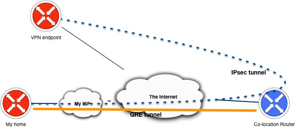
During the implementation of using my own public IP space on my home server I ran into a weird issue of not being able to pass traffic between hosts on either side of the VPN. After investigation it seems to be a combination of factors by using GRE tunneling, a policy based site-to-site VPN rather than a route-based site-to-site VPN and the (v)SRX platform. Please note that I only tested this on the Virtual SRX platform, not on physical appliances. I did test in multiple releases of Junos, but found that it affects all that I tested (latest I tested is Junos 20.1R1.11).

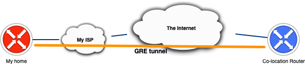
As described in the previous blog post regarding running own public IP space in your home lab behind a consumer internet connection. I run a GRE tunnel to a router that is connected via multiple peering and transit connections which allows me to advertise my own AS and IP prefixes. Then going across the internet I want to run a site-to-site VPN towards another location where back-ups of my homelab are stored.

IPsec over GRE or GRE over IPsec

The 2 variants seem to be used interchangeably if you search for this deployment online, but my use case was very much the first option. I’m running a site-to-site VPN over a GRE tunnel across the internet towards another VPN endpoint. The latter option is a much more deployed option in real life as it enables the user to support other types of network traffic that are traditionally not possible with a IPsec VPN like supporting multicast or MPLS traffic. 

The design I’m trying to implement is not very typical and (should) not (be) found in production networks (as it’s really a workaround). What I’m trying to say is that when GRE and IPsec are typically deployed end-to-end it is between the same endpoints. In my case the GRE tunnel terminates before the IPsec VPN endpoint.

Initial configuration

Let’s first set a baseline in a lab environment to test this out. I’m using my lab server running EVE-NG to set-up a lab with 2 vSRX firewalls at my Home and my Remote site. Then a vMX router simulating my ISP (just a transit for GRE traffic), a vMX router terminating my GRE tunnel and advertising the public IP prefix. Finally 2 Docker containers simulating end hosts to generate some test pings that are in the LAN subnets behind both vSRX firewalls. To keep the blog readable, full configurations are not shown, but only relevant parts.

The set-up is as shown in the diagram 

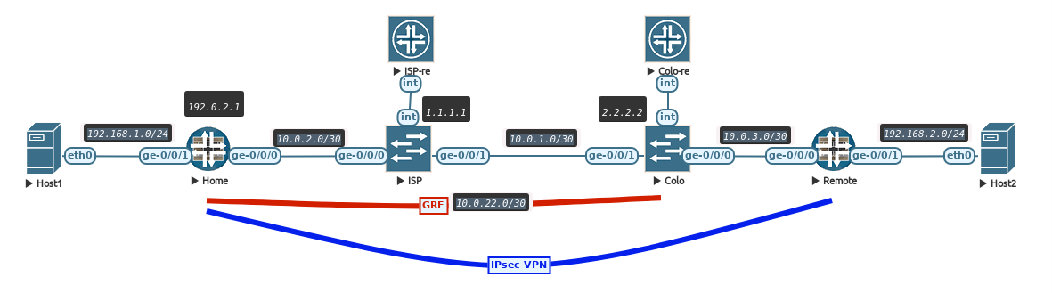
The ISP and COLO routers have full reachability with each other using OSPF so the loopbacks are reachable as if they are internet hosts. The GRE tunnel is set-up between the Home SRX and COLO router and, just like in the previous blog, using BGP to exchange a public IP prefix so my home router is reachable via that. The Home SRX has a Loopback IP of 192.0.2.1.

interfaces {
    /* ISP Uplink */
    ge-0/0/0 {
        unit 0 {
            family inet {
                address 10.0.2.2/30;
            }
        }
    }
    /* GRE to COLO router */
    gr-0/0/0 {
        unit 0 {
            clear-dont-fragment-bit;
            tunnel {
                source 10.0.2.2;
                destination 2.2.2.2;
                allow-fragmentation;
            }
            family inet {
                mtu 1476;
                address 10.0.22.2/30;
            }
        }
    }
    /* Home LAN */
    ge-0/0/1 {
        unit 0 {
            family inet {
                address 192.168.1.1/24;
            }
        }
    }
    /* Public IP address */
    lo0 {
        unit 0 {
            family inet {
                address 192.0.2.1/32;
            }
        }
    }
}
protocols {
    bgp {
        group COLO {
            type external;
            /* Export public IP prefix */
            export colo-export;
            peer-as 65000;
            neighbor 10.0.22.1;
        }

    }
}
routing-options {
    static {
        route 2.2.2.2/32 next-hop 10.0.2.1;
        route 192.0.2.0/24 discard;
    }
    router-id 3.3.3.3;
    autonomous-system 65001;
}

As shown above in the static routes. The Home SRX only knows how to reach the COLO router via the regular ISP uplink and will rely on a default route imported via BGP over the GRE tunnel for all other destinations.

root@Home> show route 

inet.0: 10 destinations, 10 routes (10 active, 0 holddown, 0 hidden)
+ = Active Route, - = Last Active, * = Both

0.0.0.0/0          *[BGP/170] 05:13:34, MED 0, localpref 100
                      AS path: 65000 I, validation-state: unverified
                    >  to 10.0.22.1 via gr-0/0/0.0
2.2.2.2/32         *[Static/5] 05:13:37
                    >  to 10.0.2.1 via ge-0/0/0.0
10.0.2.0/30        *[Direct/0] 05:13:37
                    >  via ge-0/0/0.0
10.0.2.2/32        *[Local/0] 05:13:37
                       Local via ge-0/0/0.0
10.0.22.0/30       *[Direct/0] 05:13:37
                    >  via gr-0/0/0.0
10.0.22.2/32       *[Local/0] 05:13:37
                       Local via gr-0/0/0.0
192.0.2.0/24       *[Static/5] 05:14:53
                       Discard
192.0.2.1/32       *[Direct/0] 05:14:53
                    >  via lo0.0
192.168.1.0/24     *[Direct/0] 05:13:37
                    >  via ge-0/0/1.0
192.168.1.1/32     *[Local/0] 05:13:37  
                       Local via ge-0/0/1.0

The host containers on the home and remote LAN subnets are now able to reach the internet via a simple source NAT configuration. On the remote subnet this is done via the interface IP address and on the home subnet this is done by using the public IP address (192.0.2.1). Both hosts are able to reach the loopback IP of the ISP router (remember, the Home SRX is directly connected, but only know how to reach it via the GRE tunnel received default route over BGP).

host1:/# ping 1.1.1.1
PING 1.1.1.1 (1.1.1.1) 56(84) bytes of data.
64 bytes from 1.1.1.1: icmp_seq=1 ttl=62 time=4.17 ms
64 bytes from 1.1.1.1: icmp_seq=2 ttl=62 time=2.83 ms
64 bytes from 1.1.1.1: icmp_seq=3 ttl=62 time=3.18 ms

Host2:/# ping 1.1.1.1
PING 1.1.1.1 (1.1.1.1) 56(84) bytes of data.
64 bytes from 1.1.1.1: icmp_seq=1 ttl=62 time=12.8 ms
64 bytes from 1.1.1.1: icmp_seq=2 ttl=62 time=2.02 ms
64 bytes from 1.1.1.1: icmp_seq=3 ttl=62 time=1.57 ms

IPsec configuration

As this set-up is replicating my own home set-up. I am using a policy based VPN, because the remote side is using a device which does not support a route based VPN (using an st0 interface on Junos or similar on other vendors).

The most important part in the config is the exclusion of the traffic dedicated for the IPsec VPN (192.168.1.0/24 destined for 192.168.2.0/24) of the NAT rule, as I just want the 2 subnets to communicate directly without translation.

Second is the policy part, where the policy is used to trigger the encapsulation of traffic in ESP packets for the traffic between the 2 subnets.

security {
    ike {
        proposal ike-vpnProposal {
            authentication-method pre-shared-keys;
            dh-group group5;
            authentication-algorithm sha1;
            encryblogion-algorithm aes-128-cbc;
            lifetime-seconds 28800;
        }
        policy ike-vpnPolicy {
            mode main;
            proposals ike-vpnProposal;
            pre-shared-key ascii-text blablabla;
        }
        gateway gw-blog {
            ike-policy ike-vpnPolicy;
            address 10.0.3.2;
            external-interface lo0.0;
            local-address 192.0.2.1;
        }
    }
    ipsec {
        proposal ipsec-vpnProposal {
            protocol esp;
            authentication-algorithm hmac-sha1-96;
            encryblogion-algorithm aes-128-cbc;
            lifetime-seconds 3600;
        }
        policy ipsec-vpnPolicy {
            perfect-forward-secrecy {
                keys group5;
            }
            proposals ipsec-vpnProposal;
        }
        vpn vpn-blog {
            ike {
                gateway gw-blog;
                ipsec-policy ipsec-vpnPolicy;
            }
            establish-tunnels immediately;
        }
    }

    address-book {
        untrust {
            address remote-network 192.168.2.0/24;
            attach {
                zone untrust;
            }
        }
        trust {
            address home-network 192.168.1.0/24;
            attach {
                zone trust;
            }
        }
    }
    nat {
        source {
            pool internet {
                address {
                    192.0.2.1/32;
                }
            }
            rule-set trust-to-untrust {
                from zone trust;
                to zone untrust;
                rule vpn {
                    match {
                        source-address 192.168.1.0/24;
                        destination-address 192.168.2.0/24;
                    }
                    then {
                        source-nat {
                            off;
                        }
                    }
                }
                rule all {
                    match {
                        source-address 0.0.0.0/0;
                    }
                    then {
                        source-nat {
                            pool {
                                internet;
                            }
                        }
                    }
                }
            }
        }
    }
    policies {
        from-zone trust to-zone untrust {
            policy vpn2 {
                match {
                    source-address home-network;
                    destination-address remote-network;
                    application any;
                }
                then {
                    permit {
                        tunnel {
                            ipsec-vpn vpn-blog;
                            pair-policy vpn;
                        }
                    }
                }
            }
            policy permit-all {
                match {
                    source-address any;
                    destination-address any;
                    application any;
                }
                then {
                    permit;
                }
            }
        }
        from-zone untrust to-zone trust {
            policy vpn {
                match {
                    source-address remote-network;
                    destination-address home-network;
                    application any;
                }
                then {
                    permit {
                        tunnel {
                            ipsec-vpn vpn-blog;
                            pair-policy vpn2;
                        }
                    }
                }
            }
        }
    }
}

Now the VPN is configured and active we can test reachability

root@Home> show security ipsec security-associations 
  Total active tunnels: 1     Total Ipsec sas: 1
  ID    Algorithm       SPI      Life:sec/kb  Mon lsys Port  Gateway   
  <2      ESP:aes-cbc-128/sha1 7df48801 2520/ unlim - root 500 10.0.3.2        
  >2      ESP:aes-cbc-128/sha1 eea8273a 2520/ unlim - root 500 10.0.3.2  

The behavior seen is very strange. The Home LAN host cannot access the Remote LAN host, but from the Remote to Home all seems to work fine!

host1:/# ping 192.168.2.2
PING 192.168.2.2 (192.168.2.2) 56(84) bytes of data.
^C
--- 192.168.2.2 ping statistics ---
3 packets transmitted, 0 received, 100% packet loss, time 2044ms


Host2:/# ping 192.168.1.2
PING 192.168.1.2 (192.168.1.2) 56(84) bytes of data.
64 bytes from 192.168.1.2: icmp_seq=1 ttl=62 time=3.27 ms
64 bytes from 192.168.1.2: icmp_seq=2 ttl=62 time=3.36 ms
64 bytes from 192.168.1.2: icmp_seq=3 ttl=62 time=3.67 ms

Weird IPsec over GRE issue

The problem seems to be with how the SRX policy engine encapsulates traffic. The ‘double encapsulation’ of both ESP and GRE does not seem to be working when the GRE and ESP endpoint are not the same IP address. In this case the GRE tunnel terminates well before the IPsec endpoint.

In the session flow output, everything seems to be okay with next-hop correctly showing the GRE tunnel, but no traffic is showing up on the other side.

root@Home> show security flow session    

Session ID: 162, Policy name: vpn2/4, Timeout: 58, Valid
  In: 192.168.1.2/152 --> 192.168.2.2/1;icmp, Conn Tag: 0x0, If: ge-0/0/1.0, Pkts: 1, Bytes: 84, 
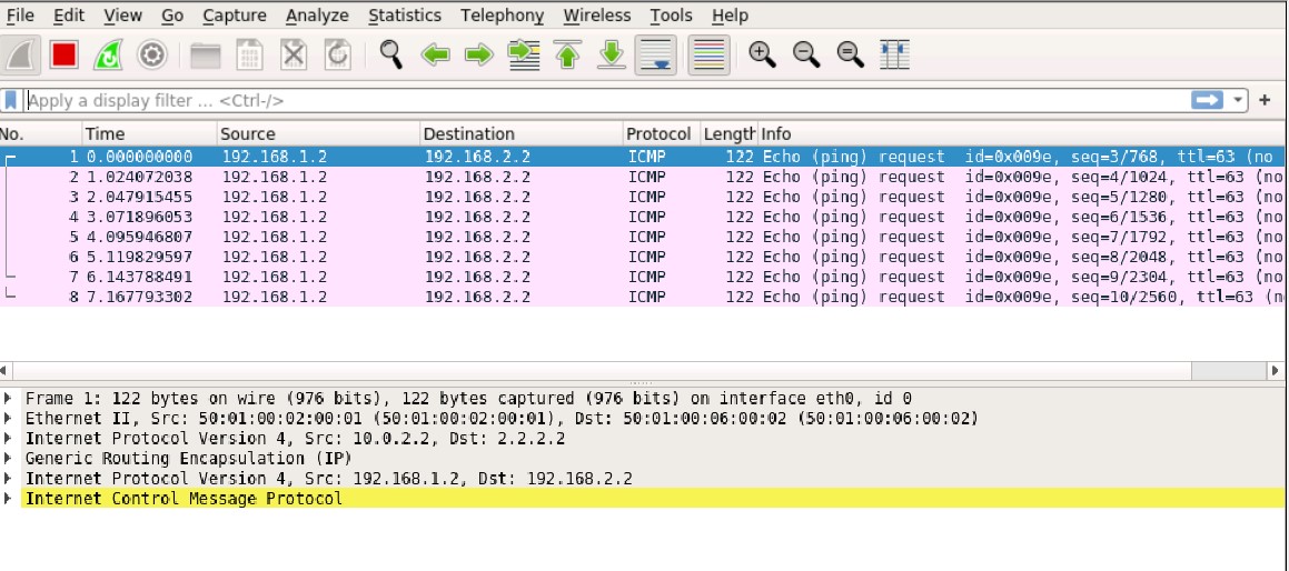
  Out: 192.168.2.2/1 --> 192.168.1.2/152;icmp, Conn Tag: 0x0, If: gr-0/0/0.0, Pkts: 0, Bytes: 0, 

This is clearly seen in a packet capture on the Home SRX ISP uplink interface. Only GRE packets are seen, but they are unencrypted!

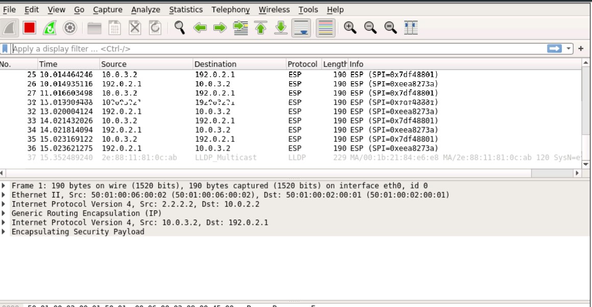
When the ping is initiated from the remote side, the ping is working fine. Even the return traffic is correctly encapsulated in the IPsec tunnel with ESP.

Solution(s)

The limitation seems to be the combination of using a policy based VPN with a GRE tunnel as underlay that does not terminate on the same device/IP as the IPsec tunnel. Again the use case for this is limited and I would not see a lot of people running into this. Of course there are always workarounds to solve this!

1. Route Based

The first solution would be to use a route based VPN. When traffic is routed across the IPsec VPN. The next-hop interface in the flow engine then changes from the gr-0/0/0 tunnel interface to the st0 interface and the traffic is correctly encrypted and encapsulated in ESP before being sent over the GRE tunnel.

As mentioned before, my remote side does not support a route based VPN so this does not solve my problem.

2. Looping through the vSRX with a logical tunnel

This is a bit of a far stretched solution that I would not typically recommend using in a production environment, but it works fine and I’ve successfully used this set-up for a few months now.

My goal is that I need another device or virtual device in front of the GRE tunnel, so the next-hop interface changes from the GRE tunnel to something else. I ultimately settled on creating a virtual-router (VRF-lite like) routing-instance on the vSRX. Setting up the GRE tunnel there and looping the traffic back into the default routing-instance using a logical-tunnel.

I will explain the configuration steps involved for this in the next post!

Using my own public IP space on a regular internet connection with a Juniper SRX

Recently I purchased new servers for my home lab (topic for more posts to follow when everything is fully done). I wanted to use these servers to run a number of workloads (mainly virtual machines) and I wanted to use the public IP space I recently got for that. Of course my consumer internet connection does not support setting up BGP and I did not want to spend a lot more money on a ‘business internet’ option.

I was discussing this with a friend and he offered me to use the router in a co-location he has. This allowed me to set-up a GRE tunnel to the router and advertise my prefix. Resulting in the following topology:

In the initial set-up I’m using a virtual firewall, as I’m moving my home lab in a few months and want to deploy this on a physical firewall then. My first attempt was to use pfSense. I’ve been using pfSense in the past a lot with great pleasure. It has great firewall, NAT and VPN features, but routing is not its strongest. I was successful in setting up OpenBGPd, but I found the GUI integration limited. The GRE tunnelling support was where I got stuck. One important missing piece on the pfSense part was that it is not possible to configure IPv6 addresses on the GRE tunnel interface (overlay IP addresses). I managed to get it working on link-local addresses, but this required special static routes to be added and I didn’t think it was an elegant solution. Without having proper overview of the functioning of the system (both on the GRE tunnel and the BGP part) I abandoned the pfSense option.

vSRX

I then deployed a Juniper vSRX firewall. Now this is not a free option, but as I work for Juniper, I really liked having Junos at this critical place in my own home network. I’m using the 60-day trial license that anyone can get, including the latest virtual appliances on the Juniper website (https://www.juniper.net/us/en/dm/free-vsrx-trial/). In the final set-up I’m probably going to use a SRX300 physical appliance that should give me enough forwarding performance for my 500/40Mbps cable connection.

In the past the vSRX was based on a FreeBSD VM running on top of a Linux guest OS. Where the data-plane processes were running on top of Linux to utilise DPDK to accelerate packet processing.

vSRX2 architecture

This enabled the use of much better multi-core processing support in the Linux kernel, while still using the FreeBSD based Junos OS. The downside was that booting the appliance took a lot of time (7-10 minutes). It also required to have ‘Promiscuous mode’ enabled to connect to the fxp0 out-of-band management interface, as this was a virtual NIC with another mac address inside the FreeBSD VM.

The latest version of vSRX called vSRX3 or vSRX 3.0 surprisingly does not use Linux anymore, but is fully based on FreeBSD 11. Making use of the improvements in FreeBSD regarding multi-core processing and support for DPDK. It also means that performance did not change (may have even improved in some cases) when this transition was made and greatly improving boot times (about a minute now). Even with only 2 CPU cores (still separating control- and data-plane processes) the vSRX performs great and is well suited for my use case.

vSRX3 architecture

As there is no virtual machine involved in this architecture. The fxp0 interface is reachable again without having to enable Promiscuous mode in ESXi environments.

My set-up did not require the use of more advanced features like SR-IOV, because my bandwidth requirements are considered quite low (1Gbps is more than enough for my home network!)

Tip: To know the difference if you are running a vSRX3 or a previous generation, take a look at the output of ‘show version’. If ‘vSRX’ is written with uppercase letters you are running vSRX3, if ‘vsrx’ is written in all lowercase, you are running a previous generation.

Fun fact: Did you know the first version of this product was called Firefly Perimeter?

Diagrams and more details found at: https://www.juniper.net/documentation/en_US/vsrx/information-products/topic-collections/release-notes/19.1/topic-98044.html#jd0e101

GRE configuration

The set-up for GRE and BGP is rather simple if you are used to Junos configuration. The GRE tunnel interface is available on the vSRX by default and no configuration is necessary to enable it.

First I configured the GRE interface. The important part here is that I ran into some MTU/fragmentation issues as I am transiting a default 1500 byte MTU infrastructure (also known as the Internet ;). Which is why I enabled the allow-fragmentation and clear-dont-fragment-bit knobs. As I will want to have all my internet facing traffic to use the GRE tunnel, the only routing configuration I need is to know where to find the GRE tunnel destination. This is why a /32 static route is configured.

All IP addressing used in these examples are specified as prefixes used for documentation.

interfaces {
gr-0/0/0 {
unit 0 {
clear-dont-fragment-bit;
description "GRE to Colo";
tunnel {
source 203.0.113.1;
destination 198.51.100.1;
allow-fragmentation;
}
family inet {
mtu 1476;
address 192.0.2.253/31;
}
family inet6 {
mtu 1476;
address 2001:db8:1::1/64;
}
}
}
}
routing-options {
static {
route 198.51.100.1/32 next-hop 203.0.113.2;
}
}

As the GRE interface is just a regular interface, we should configure this interface to belong to a security zone. In this case it’s my untrust zone as I connect directly to the Internet. I allow BGP traffic to access this interface as we will configure this later. I do not include any security policy configuration here, as they are just default (allow all traffic from trust to untrust).

security {
flow {
tcp-mss {
all-tcp {
mss 1340;
}
}
}
zones {
security-zone untrust {
interfaces {
gr-0/0/0.0 {
host-inbound-traffic {
protocols {
bgp;
}
}
}
}
}
}
}

One key knob here is that I have to specify a TCP MSS value that is much lower than normal. This is because I need to account for a GRE+IP header overhead, but I also have an IPsec tunnel configured that adds overhead. There are special commands here to just change the MSS size for GRE tunnels, but they are designed for the GRE over IPsec use-case. This is IPsec over GRE.

In my case an MSS size of 1366 works, but this is not an easy job to determine, as the ESP overhead on a packet varies on the packet size. I tried an ICMP ping with DF-bit set and up to 1378 bytes, my ping reply came back. This means 1378 + ICMP (8b) + IP (20b) = 1406 bytes, or 94 bytes of total overhead

MSS: MTU – IP (20b) – TCP (20b) = 1460 bytes – All-overhead (94b) = 1366 bytes

Cisco has a great IPsec overhead calculator https://cway.cisco.com/ipsec-overhead-calculator/

Online I found varying safe numbers. I’ve set it to 1340 to also accommodate the additional 20 bytes on an IPv6 header. Please comment below your recommendation for MSS size!

BGP configuration

Finally it’s time to set-up some dynamic routing. In this case, as I wanted to advertise my own Autonomous System (AS) as well. I wanted to originate BGP from my house and the router in the co-location to act as transit provider for me. So let’s setup a pretty standard EBGP configuration. Again BGP is included in any vSRX license.

protocols {
bgp {
group colo-v4 {
type external;
import colo-ipv4-in;
family inet {
unicast;
}
export colo-ipv4-out;
peer-as 65001;
neighbor 192.0.2.254;
}
group colo-v6 {
type external;
import colo-ipv6-in;
family inet6 {
unicast;
}
export colo-ipv6-out;
peer-as 65001;
neighbor 2001:db8:1::2;
}
log-updown;
}
}
routing-options {
router-id 192.0.2.1;
autonomous-system 64999;
}

As BGP is already specified as host-inbound-traffic in the security zones configuration, no additional policy is required. This does mean that all BGP traffic is allowed. Of course it’s best practice to limit the source address of the BGP traffic to only the neighbors configured. For that the vSRX supports regular control plane security by applying a firewall filter configuration to the Loopback interface (no IP address required if you don’t want it). 

Of course policies are the most important part of any BGP configuration. I’m not interested in receiving a full BGP table so a default route will do fine for both IPv4 and IPv6. Second I need to advertise my own IP space from my own AS. To originate the prefixes I created 2 static routes to advertise the entire subnet, so I can use that later.

policy-options {
policy-statement colo-ipv4-in {
term allow-default {
from {
route-filter 0.0.0.0/0 exact;
}
then accept;
}
then reject;
}
policy-statement colo-ipv4-out {
term my-subnet {
from {
protocol static;
route-filter 192.0.2.0/24 exact;
}
then accept;
}
then reject;
}
policy-statement colo-ipv6-in {
term allow-default {
from {
route-filter ::/0 exact;
}
then accept;
}
then reject;
}
policy-statement colo-ipv6-out {
term my-subnet {
from {
protocol static;
route-filter 2001:db8:abc::/48 exact;
}
then accept;
}
then reject;
}
}
routing-options {
rib inet6.0 {
static {
route 2001:db8:abc::/48 discard;
}
}
static {
route 192.0.2.0/24 discard;
}
}

RIPE

Now establishing a dynamic routing configuration is one thing. To have your prefix be accepted by any upstream networks, you have to make sure your administration is in place. As I live in Europe, my IP resources come from RIPE. 

By the way: If you want to learn more on RIPE, RIPE NCC and Routing Security, make sure you listen to the episode of the Routing Table podcast we recorded with Nathalie Trenaman on these topics!

You have to make sure there is a ROUTE object created for your prefixes which also specifies what the origin AS will be for these prefixes. While you are there and signed in anyway, make sure you also create ROA objects so RPKI will mark your prefixes as valid when they originate your AS!

Most providers will have some form of filtering applied to their peers, which means that I also had to make sure that my upstream provider accepted my AS and prefixes. This meant that I had to be included in the AS-SET object of my upstream provider.

I typically use the bgpq3 tool to verify if my objects are correctly set (no guarantees, as your providers can use different tools to collect this information)

NAT

Now to finally make use of the prefix now it’s advertised and accepted. I set-up a simple source NAT rule so my egress traffic uses an IP address in my own subnet as source for browsing the web.

The SRX has a default source NAT rule in place to accept all traffic from the trust zone going to untrust and use the interface IP address as source IP. This I want to have changed to an IP from my own subnet, which requires a pool to be created (even it’s only 1 IP that everything is translated to).

security {
nat {
source {
pool internet {
address {
192.0.2.1/32;
}
}
rule-set trust-to-untrust {
from zone trust;
to zone untrust;
rule all-trust {
match {
source-address 0.0.0.0/0;
}
then {
source-nat {
pool {
internet;
}
}
}
}
}
}
}
}

Done!?

Now I can browse the internet from my own IP space from my own home internet connection!

Stay tuned for another blog about the funny limitation I ran into when I configured an IPsec VPN. That required having to reconstruct quite a bit of this set-up to work around it!


Nested Virtualization

A typical Network Virtualization demo is difficult as you need quite some hypervisor hosts to run some VMs on and interconnect them using Overlays. I solve this using nested virtualization. This means that I run a hypervisor running on another. This gives me the flexibility that my physical nodes, or “hypervisor underlay” if you will, can scale easily and I’m independent of them.

My physical cluster consists of 2 nodes running ESXi with vCenter. On top of that I’m running 4 other ESXi hosts divided in 2 “virtual” clusters and 4 KVM hosts as Contrail Compute Nodes.

How does this work?

This technology works using Intel’s VT-x (which is hardware assisted virtualization) and EPT (to virtualise memory allocations). This combination works since the “Nehalem” archnested1
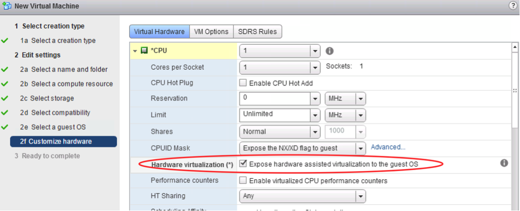
itecture (released 2008). The technology is ported to the more “Desktop” oriented CPU’s as well, so there is a good chance your notebook supports it as well. Since the Haswell architecture the nested virtualization works even better as Intel now supports VMCS Shadowing for nested VMs, which creates a data structure in memory per VM (and now supports nested VMs as well, which used to be a software effort).

Memory is the biggest burden in these nested set-ups. CPU performance is always hardware assisted, so nested VMs almost feel the same as regular VMs. The problem is that ESXi itself requires 4GB of memory to run, it requires around 2GB to run properly. So get at least a 32GB server, otherwise you run out of memory very fast!

The amount of nested virtualization is technically unlimited. So you could have 2, 3 or 4 levels deep. Where at some point to use-case becomes very small of course. The same goes for 32-bit and 64-bit machines. As long as your physical CPU is a 64-bit one (32-bit CPU’s do not support VT-X or EPT) you are able to run 32-bit and 64-bit guests inside a nested ESXi installation running on top of ESXi.


Set-up

I’m using ESXi as my main hypervisor as it has the best management  tools currently out and most of my customers are using it. This gives me a stable foundation. So this set-up is based on the ESXi version of configuration. I’m using the latest version of ESXi as of this writing (5.5u2). To set-up nested virtualisation properly you have to use at least Virtual Machine hardware version 9 or 10. This means you have to configure this using the vSphere Web Client and therefore vCenter Server (Appliance) is also required to be running in your lab. I would also recommend to give your virtual ESXi at least 2 vCPU’s (no performance difference in allocating cores or sockets) and sufficient memory. Remember that ESXi will consume about 2GB to run for itself and the rest you can allocate to VM’s. Depending on the amount of nested VM’s you want to run I gave 6GB of memory to my ESXi as I’m only running 3-4 guest VM’s on this nested hypervisor.

CPU

The most important setting is when you open up the “CPU” panel in VM settings. There you have to enable “Expose hardware assisted virtualisation to the guest OS”. This will enable the exposure of the Intel VT-x feature towards the VM and will enable ESXi to recognize a virtualization capable host. If this checkbox is greyed out, it means your CPU is not suitable for nested virtualization.

(The same steps are required to install nested KVM inside ESXi, Hyper-V may require some additional tweaking)

Nested2

Networking

After installing ESXi inside the VM you are almost up and running! First of all you probably want to allow VLAN tagging to go towards the nested ESXi and for VLAN tags to come from the vSwitch running inside the nested ESXi. This requires a port group that is set for VLAN Trunking. I’m using a Standard vSwitch, not a Distributed vSwitch (DVS) on my physical cluster, because of the fact that the vCenter server has to be up and running to be able to power on a VM on a DVS. Because I will be playing around with this environment I can’t rely on vCenter being up all the time. So therefore I chose to use Standard vSwitches on the physical cluster. As I will experiment with networking features on the nested ESXi installations. To create a VLAN trunking capable Port Group, you have to create this on each physical host separately and allow a VLAN tag of “all” or “4095”.

Nested3

This will make sure that my network inside the nested ESXi installation is VLAN tagging capable!

Now before this will work fine, we need to change one more setting on our physical cluster ESXi installation.ESXi by default considers itself to be the master of the network (at least inside the ESXi environment). Because ESXi is generating the MAC addresses that the VMs use it doesn’t allow any other MAC addresses to enter the vSwitch coming from a virtual interface. This is a great security feature and definitely helps a lot in preventing all kinds of network attacks to be based from inside the VM. Because we will be having a whole new ESXi installation that is generating it’s own MAC addresses we do want to allow unknown MAC addresses to enter on the virtual interfaces connecting to the nested ESXi VMs. To enable this you have to allow the “Promiscuous mode” on the vSwitch or on the port groups you applied to the ESXi VM. I enabled it on the vSwitch itself, just to be sure not having to worry about it when I create a new port group. Remember to change this setting on all of your physical hosts when using a Standard vSwitch. Make sure to change “Promiscuous mode” to “accept” and that “Forged transmits” and “MAC address changes” are also set to “accept”, but that’s the default.

Nested4

Now Promiscuous mode does impact performance on your ESXi server. ESXi has no concept of MAC learning like a regular Ethernet Switch. This means that when we disable the security control of MAC addresses being assigned to the virtual interfaces (promiscuous mode) we will flood all traffic to all of the ports inside the vSwitch. With regular feature testing you won’t generate much data traffic, but when you do get to a few Mbps of traffic, this could impact CPU performance quite a lot. There is a plug-in that will enable MAC learning on interfaces that you configure it for. This does require a Distributed Virtual Switch to be running in the physical cluster. You can find it, together with implementation details, here: https://labs.vmware.com/flings/esxi-mac-learning-dvfilter

I would not recommend using it in tests with a lot of NFV appliances (virtual firewalls, virtual routers, etc.), as the entries learnt through this filter will not age out. This means that when your nested Guest VMs are moving a lot, it will register that MAC address on each port meaning the performance improvements will go away. If you have a stable environment then this MAC learning feature will be beneficial.  More details are found in this excellent blog: http://www.virtuallyghetto.com/2014/08/new-vmware-fling-to-improve-networkcpu-performance-when-using-promiscuous-mode-for-nested-esxi.html

VMtools

The final optimization that can be done when you are running ESXi as a VM is to run VMware Tools. This will make sure that a graceful shutdown can be done and makes your life a bit easier when it comes to IP addressing and have visibility inside vCenter. The default VMware tools do not support ESXi, you require to have the version installed found here: https://labs.vmware.com/flings/vmware-tools-for-nested-esxi

Summary

When everything is installed I highly recommend creating a separate cluster for these nested hypervisors and keep your physical cluster clean. Now you are ready to deploy VM’s just as you are used to, but now inside a safe environment where you can start breaking things!


Happy Labbing!

« Older posts Newer posts »

© 2024 Rick Mur

Theme by Anders NorenUp ↑