Limitless Networking

Category: Data Center

EVPN Configuration

In my last blog I explained the features and use cases of the EVPN technology. In this blog I want to show how easy it is to configure, enable and expand EVPN. The configuration is focused on the Juniper MX platform, but as Junos is the single operating system across the entire Juniper portfolio, configuration on other platforms (like EX9200) is equal.

Design

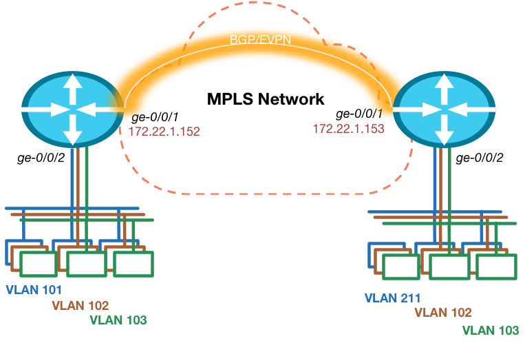
The topology is really simple. I’m using 2 routers in this example, so multi-homing is not in scope. Each router has an Ethernet segment connected that consists of multiple VLANs on each side. There is 1 VLAN ID that is not equal on both sides, so this has to be taken care of.

EVPNtopology

Prepare for EVPN

To make sure we can start creating our VPN, we have to ensure the foundation is in place. This means we need IP reachability to the other Data Center routers loopback address and we need BGP with the EVPN address family enabled. The Junos release I’m testing with needs a special knob to be enabled to ensure packet lookups are done in the right way. Other versions will see this knob disappear as it is default moving forward.

routing-options {
    autonomous-system 64999;
    forwarding-table {
        chained-composite-next-hop {
            ingress {
                evpn;
            }
        }
    }
}
protocols {
    mpls {
        interface ge-0/0/1.0;
    }
    bgp {
        group INTERNAL {
            type internal;
            local-address 172.22.250.152;
            family inet-vpn {
                unicast;
            }
            family evpn {
                signaling;
            }
            neighbor 172.22.250.153;
        }
    }
    ospf {
        area 0.0.0.0 {
            interface lo0.0 {
                passive;
            }
            interface ge-0/0/1.0;       
        }
    }
    ldp {
        interface ge-0/0/1.0;
    }
}

Interface ge-0/0/1 is the one connected to the MPLS network and we configured an iBGP neighbor for both the Layer 3 VPN and EVPN address families to exchange layer 2 and layer 3 routes with each other.

We use OSPF as internal routing protocol, but in this simple topology it could’ve been a static route as well.

VLAN Based Service

There are 2 options to configure EVPN. The first option is to configure a separate EVPN Instance or EVI for each VLAN/Bridge-Domain. This brings the best separation of traffic, MAC address advertisements and give full control over flooding of broadcast traffic on a per VLAN/Bridge-Domain basis. The VLAN ID of traffic that is sent between the 2 PE routers will be set to 0.

EVPNoption1A Route-Target and Route Distinguisher is created for each EVI and therefore each VLAN has it’s own MPLS Label.

This could potentially cause scaling issues, as PE routers have a limit on the number of VPNs that can be configured.

The following is an example of the configuration for our topology.

interfaces {
    ge-0/0/2 {
        flexible-vlan-tagging;
        encapsulation flexible-ethernet-services;
        unit 101 {
            encapsulation vlan-bridge;
            vlan-id 101;
        }
        unit 102 {
            encapsulation vlan-bridge;
            vlan-id 102;
        }
        unit 103 {
            encapsulation vlan-bridge;
            vlan-id 103;
        }
    }
}
routing-instances {
    BD1 {
        instance-type evpn;
        interface ge-0/0/2.101;
        route-distinguisher 1001:1001;
        vrf-target target:1001:1001;
    }
    BD2 {
        instance-type evpn;
        interface ge-0/0/2.102;
        route-distinguisher 1002:1002;
        vrf-target target:1002:1002;
    }
    BD3 {
        instance-type evpn;
        interface ge-0/0/2.103;
        route-distinguisher 1003:1003;
        vrf-target target:1003:1003;
    }
}

The commands “flexible-ethernet-services” and “flexible-vlan-tagging” on the interface allow us to use this interface for a variety of services. This means we can use single or double-tagged interfaces and we can configure both layer 2 bridging as layer 3 sub-interfaces on  this single physical interface. One of the very strong features of the MX platform!

As you  can see the VPN configuration is very easy! We just make sure the right interface is in the VPN and we assign a RD and RT value to it and we’re done!

As we have a single-homed scenario, there is no configuration necessary. The ESI (as discussed in my previous blog) is by default set to 0 on single-homed routers and doesn’t have to be different on the other end, because of the single-home setting, which is enabled by default.

VLAN Aware Service

The second option is more flexible to use. This is the VLAN Aware service. This option allows multiple VLANs and Bridge-Domains to cross a single EVPN Instance (EVI). This improves scaling and still allows for proper separation. The VLAN ID is now encapsulated in the packet. To ensure proper ECMP forwarding in the MPLS network an MPLS label is assigned per VLAN ID, so that traffic will be load balanced per VLAN and not per EVI.

EVPNoption2The configuration for this service is a bit more complicated, but still fairly simple and also still allows for VLAN translation! Even MAC address overlap is allowed within this service between different VLANs/Bridge-Domains.

interfaces {
    ge-0/0/2 {
        flexible-vlan-tagging;
        encapsulation flexible-ethernet-services;
        unit 0 {
            family bridge {
                interface-mode trunk;
                vlan-id-list [ 101 102 103 ];
                vlan-rewrite {
                    translate 211 101;
                }
            }
        }
    }
}
routing-instances {
    EVPN {
        instance-type virtual-switch;
        interface ge-0/0/2.0;
        route-distinguisher 1000:1000;
        vrf-target target:1000:1000;
        protocols {
            evpn {
                extended-vlan-list [ 101 102 103 ];
            }
        }
        bridge-domains {
            NETWORK1 {
                domain-type bridge;
                vlan-id 101;
            }
            NETWORK2 {
                domain-type bridge;
                vlan-id 102;
            }
            NETWORK3 {
                domain-type bridge;
                vlan-id 103;
            }                           
        }
    }
}

As you can see we also ensure the VLAN translation is taken care of. We could use VLAN normalization in this case, which means we use a different “unique” VLAN ID within the EVPN service and use VLAN translation on each side to ensure the local side has the right encapsulation.

Summary

This blog showed you how easy and how flexible EVPN configuration on Junos is and how fast we can set-up a optimal Layer 2 Data Center Interconnect. In the following blogs I will discuss multi-homing and Layer 3 integration to ensure all-active routing across Data Centers.
EVPN (RFC 7432) Explained

EVPN or Ethernet VPN is a new standard that has finally been given an RFC number. Many vendors are already working on implementing this standard since the early draft versions and even before that Juniper already used the same technology in it’s Qfabric product. RFC 7432 was previously known as: draft-ietf-l2vpn-evpn.

The day I started at Juniper I saw the power of the EVPN technology which was already released in the MX and EX9200 product lines. I enabled the first customers in my region (Netherlands) to use it in their production environment.

EVPN is initially targeted as Data Center Interconnect technology, but is now deployed within Data Center Fabric networks as well to use within a DC. In this blog I will explain why to use it, how the features work and finally which Juniper products support it.

Why?

Data Center interconnects have historically been difficult to create, because of the nature of Layer 2 traffic and the limited capabilities to control and steer the traffic. When I have to interconnect a Data Center today I have a few options that often don’t scale well or are proprietary. Some examples:

  • Dark Fiber
  • xWDM circuit
  • L2 service from a Service Provider
  • VPLS
  • G.8032
  • Cisco OTV or other proprietary solutions

Most options also only work well in a point to point configuration (2 data centers) like Dark Fiber or xWDM circuits or only with a few locations/sites (VPLS).

Only the proprietary solutions have a control-plane that controls the learning and distribution of MAC addresses. All others are technically just really long Ethernet cables that interconnect multiple Data Centers.

Now why is that so dangerous? 

I’ve had numerous customers with complete Data Center outages because of this fact. No matter which solution you pick that does not offer a control-plane for the MAC learning, when problems occur in one DC like ARP flooding or other traffic floods. They will propagated to the other DC as well using the interconnection layer that can only protect it with features like storm-control, etc. This means that impact on Layer 2 in DC1 impacts other Data Centers. Where in most cases the other Data Center is in place because of high availability reasons.

EVPN will solve this!

How?

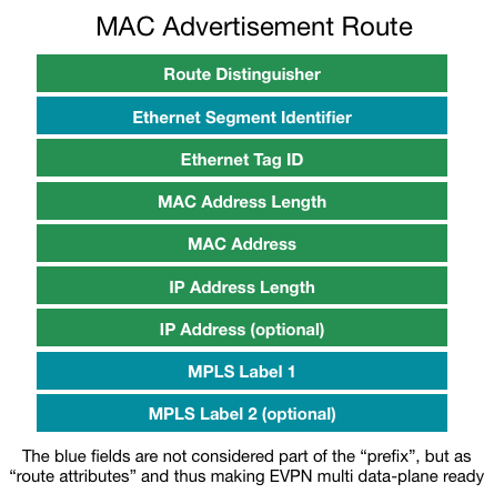
EVPN is technically just another address family in Multi Protocol (MP) BGP. This new address family allows MAC addresses to be treated as routes in the BGP table. The entry can contain just a MAC address or an IP address + MAC address (ARP entry). This can all be combined with or without a VLAN tag as well. The format of this advertisement is shown in the drawing.

MACroute

BGP benefits

Now the immediate benefit of using BGP for this case, is that we know how well the BGP protocol scales. We won’t have any problems learning hundreds of thousands of MAC entries in the BGP table.

Route L2 traffic – All-Active Forwarding

The second benefit is that we now have MAC addresses as routing entries in our routing table and we can make forwarding decisions based on that. This means we can use multiple active paths between data centers and don’t have to block all but 1 link (which is the case in all the previously mentioned DCI technologies). The only traffic that is limited to 1 link is so-called BUM traffic (Broadcast, Unknown unicast and Multicast). For BUM traffic a Designated Forwarder (DF) is assigned per EVPN instance. This technology is not new and is also found in protocols related to TRILL and other proprietary technologies.

ARP and Unknown Unicast

ARP traffic will be treated in a different way than regular Layer 2 interconnects will do.  First of all Proxy-ARP is enabled when EVPN is enabled on an interface. The Edge gateway of the DC will respond to all ARP requests when it knows the answer to them. This immediately implies a very important rule. When an ARP request is done to an IP address the Edge router doesn’t know or when traffic is received with a Destination MAC that is unknown, the Edge gateway will drop this traffic! This limits unknown unicast flooding immediately to only a single DC, which is quite often a cause of issues. The Edge Gateway has to learn about a MAC or ARP entry from the Edge gateway in the other DC before it will allow traffic to pass.

Multi-homing

We obviously want 2 gateway devices at the edge of our Data Center. Therefore we have to support a multi-homing scenario. EVPN allows for an all-active multi-homing scenario as previously explained, because of the routing nature. Besides this we need to limit the flooding of traffic, which is the reason why we choose a Designated Forwarder per instance which is responsible for receiving and sending BUM traffic. We also support split-horizon, to prevent that traffic originating from our own Data Center does not get back in through the other Edge Gateway. This is done using the ESI field in the advertisement. An ESI is an identification for a certain “Data Center Site”. Both gateways in a single Data Center should use the same ESI number, to prevent traffic getting looped back in. Other Data Centers should use a different ESI number. This means that each Data Center will have 1 ESI number.

MAC Mobility

The EVPN feature is designed for extremely fast convergence. Another big issue within Data Center is what’s called MAC flapping and mobility. This means that when a Virtual Machine moves with it’s MAC address, the MAC needs to be re-learned within the network and the old entry should be deleted. Within a single layer 2 switch domain this happens quite fast, which is also the cause of issues, when a duplicate MAC address is found in the network. Then the same entry is learnt on two different ports causing “MAC Flapping”. EVPN solves this by introducing a counter when a MAC moves between Data Center locations. When this happens too often in a certain time period (default 5 times in 180 seconds) the MAC will be suppressed until a retry timer expires to try again. The benefit of the MAC sequence numbering is that when the Edge Gateways see an advertisement for a MAC address with a higher sequence number they will immediately withdraw the older entry, which benefits convergence time after a VM move.

Layer 3 All-Active Gateway

The last benefit I want to highlight is that, because the Edge Gateway is fully aware where hosts are located in the network, it can make the best Layer 3 forwarding decision as well. This means that Default Gateways are active on all edge gateways in all data centers. The routing decision can be taken on Layer 2 or on Layer 3, because the edge gateway is fully aware of ARP entries .

 Data Planes

Currently there is 1 standard and 2 proposals that all rely on the same control-plane technology (EVPN). The first is the current standard RFC7432 which is EVPN with MPLS as it’s data-plane. The second proposal is EVPN-VXLAN, where the same control-plane is used, but the data-plane is now either VXLAN or another Overlay technology. The third proposal is to use PBB encapsulation over an EVPN control-plane with MPLS as data-plane.

DataPlanes

What?

Finally I want to discuss which products support this technology and how you can implement it. Juniper currently implements RFC 7432 (EVPN-MPLS) on it’s MX product line, ranging from MX5 to MX2020 and on the EX9200 series switches. The EVPN-MPLS feature is designed to be used as Data Center Interconnect.

Since the MX has full programmable chips Juniper also implements several overlay technologies like VXLAN. This means we can stitch a VXLAN network, Ethernet bridge domains, L2 pseudo wires and L3 VPN (IRB interface) all together in a single EVPN instance.

Summary

All this means we have a swiss army knife full of tools to use within our Data Center and we can interconnect various network overlays and multiple data centers together using a single abstraction layer called: EVPN!

In my next blog I will demonstrate the use of EVPN on the MX platform and how easy it is to implement an optimal Data Center Interconnect!

© 2024 Rick Mur

Theme by Anders NorenUp ↑