In my last blog I explained the features and use cases of the EVPN technology. In this blog I want to show how easy it is to configure, enable and expand EVPN. The configuration is focused on the Juniper MX platform, but as Junos is the single operating system across the entire Juniper portfolio, configuration on other platforms (like EX9200) is equal.
Design
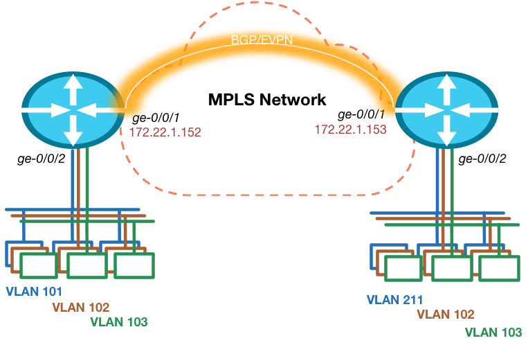
The topology is really simple. I’m using 2 routers in this example, so multi-homing is not in scope. Each router has an Ethernet segment connected that consists of multiple VLANs on each side. There is 1 VLAN ID that is not equal on both sides, so this has to be taken care of.
Prepare for EVPN
To make sure we can start creating our VPN, we have to ensure the foundation is in place. This means we need IP reachability to the other Data Center routers loopback address and we need BGP with the EVPN address family enabled. The Junos release I’m testing with needs a special knob to be enabled to ensure packet lookups are done in the right way. Other versions will see this knob disappear as it is default moving forward.
routing-options {
    autonomous-system 64999;
    forwarding-table {
        chained-composite-next-hop {
            ingress {
                evpn;
            }
        }
    }
}
protocols {
    mpls {
        interface ge-0/0/1.0;
    }
    bgp {
        group INTERNAL {
            type internal;
            local-address 172.22.250.152;
            family inet-vpn {
                unicast;
            }
            family evpn {
                signaling;
            }
            neighbor 172.22.250.153;
        }
    }
    ospf {
        area 0.0.0.0 {
            interface lo0.0 {
                passive;
            }
            interface ge-0/0/1.0;
        }
    }
    ldp {
        interface ge-0/0/1.0;
    }
}
Interface ge-0/0/1 is the one connected to the MPLS network and we configured an iBGP neighbor for both the Layer 3 VPN and EVPN address families to exchange layer 2 and layer 3 routes with each other.
We use OSPF as internal routing protocol, but in this simple topology it could’ve been a static route as well.
VLAN Based Service
There are 2 options to configure EVPN. The first option is to configure a separate EVPN Instance or EVI for each VLAN/Bridge-Domain. This brings the best separation of traffic, MAC address advertisements and give full control over flooding of broadcast traffic on a per VLAN/Bridge-Domain basis. The VLAN ID of traffic that is sent between the 2 PE routers will be set to 0.
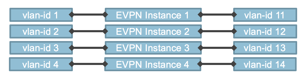 A Route-Target and Route Distinguisher is created for each EVI and therefore each VLAN has it’s own MPLS Label.
This could potentially cause scaling issues, as PE routers have a limit on the number of VPNs that can be configured.
The following is an example of the configuration for our topology.
interfaces {
    ge-0/0/2 {
        flexible-vlan-tagging;
        encapsulation flexible-ethernet-services;
        unit 101 {
            encapsulation vlan-bridge;
            vlan-id 101;
        }
        unit 102 {
            encapsulation vlan-bridge;
            vlan-id 102;
        }
        unit 103 {
            encapsulation vlan-bridge;
            vlan-id 103;
        }
    }
}
routing-instances {
    BD1 {
        instance-type evpn;
        interface ge-0/0/2.101;
        route-distinguisher 1001:1001;
        vrf-target target:1001:1001;
    }
    BD2 {
        instance-type evpn;
        interface ge-0/0/2.102;
        route-distinguisher 1002:1002;
        vrf-target target:1002:1002;
    }
    BD3 {
        instance-type evpn;
        interface ge-0/0/2.103;
        route-distinguisher 1003:1003;
        vrf-target target:1003:1003;
    }
}
The commands “flexible-ethernet-services” and “flexible-vlan-tagging” on the interface allow us to use this interface for a variety of services. This means we can use single or double-tagged interfaces and we can configure both layer 2 bridging as layer 3 sub-interfaces on this single physical interface. One of the very strong features of the MX platform!
As you can see the VPN configuration is very easy! We just make sure the right interface is in the VPN and we assign a RD and RT value to it and we’re done!
As we have a single-homed scenario, there is no configuration necessary. The ESI (as discussed in my previous blog) is by default set to 0 on single-homed routers and doesn’t have to be different on the other end, because of the single-home setting, which is enabled by default.
VLAN Aware Service
The second option is more flexible to use. This is the VLAN Aware service. This option allows multiple VLANs and Bridge-Domains to cross a single EVPN Instance (EVI). This improves scaling and still allows for proper separation. The VLAN ID is now encapsulated in the packet. To ensure proper ECMP forwarding in the MPLS network an MPLS label is assigned per VLAN ID, so that traffic will be load balanced per VLAN and not per EVI.
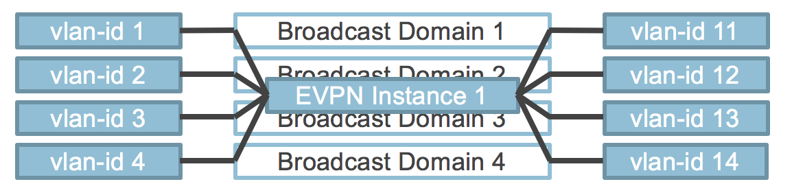 The configuration for this service is a bit more complicated, but still fairly simple and also still allows for VLAN translation! Even MAC address overlap is allowed within this service between different VLANs/Bridge-Domains.
interfaces {
    ge-0/0/2 {
        flexible-vlan-tagging;
        encapsulation flexible-ethernet-services;
        unit 0 {
            family bridge {
                interface-mode trunk;
                vlan-id-list [ 101 102 103 ];
                vlan-rewrite {
                    translate 211 101;
                }
            }
        }
    }
}
routing-instances {
    EVPN {
        instance-type virtual-switch;
        interface ge-0/0/2.0;
        route-distinguisher 1000:1000;
        vrf-target target:1000:1000;
        protocols {
            evpn {
                extended-vlan-list [ 101 102 103 ];
            }
        }
        bridge-domains {
            NETWORK1 {
                domain-type bridge;
                vlan-id 101;
            }
            NETWORK2 {
                domain-type bridge;
                vlan-id 102;
            }
            NETWORK3 {
                domain-type bridge;
                vlan-id 103;
            }
        }
    }
}
As you can see we also ensure the VLAN translation is taken care of. We could use VLAN normalization in this case, which means we use a different “unique” VLAN ID within the EVPN service and use VLAN translation on each side to ensure the local side has the right encapsulation.
Summary
This blog showed you how easy and how flexible EVPN configuration on Junos is and how fast we can set-up a optimal Layer 2 Data Center Interconnect. In the following blogs I will discuss multi-homing and Layer 3 integration to ensure all-active routing across Data Centers.

Leave a Reply